EasyManua.ls Logo

MSI K8M Neo-V User Manual

MSI K8M Neo-V
92 pages
To Next Page IconTo Next Page
Page #1 background imageLoading...
Page #1 background image
i
FCC-B Radio Frequency Interference Statement
This equipment has been tested and found to comply with the limits for a class B digital device, pursuant to part 15 of
the FCC rules. These limits are designed to provide reasonable protection against harmful interference when the
equipment is operated in a commercial environment. This equipment generates, uses and can radiate radio frequency
energy and, if not installed and used in accordance with the instruction manual, may cause harmful interference to
radio communications. Operation of this equipment in a residential area is likely to cause harmful interference, in
which case the user will be required to correct the interference at his own expense.
Notice 1
The changes or modifications not expressly approved by the party responsible for compliance could void the users
authority to operate the equipment.
Notice 2
Shielded interface cables and A.C. power cord, if any, must be used in order to comply with the emission limits.
VOIR LA NOTICE DNSTALLATION AVANT DE RACCORDER AU RESEAU.
Micro-Star International
MS-7032
This device complies with Part 15 of the FCC Rules. Operation is subject to the following two conditions:
(1) this device may not cause harmful interference, and
(2) this device must accept any interference received, including interference that may cause undesired operation
G52-M7032X2
Question and Answer IconNeed help?

Do you have a question about the MSI K8M Neo-V and is the answer not in the manual?

MSI K8M Neo-V Specifications

General IconGeneral
BrandMSI
ModelK8M Neo-V
CategoryMotherboard
LanguageEnglish

Summary

FCC-B Radio Frequency Interference Statement

Notice 1

Explains modifications void user authority to operate.

Notice 2

Specifies use of shielded cables and power cord.

Safety Instructions

General Safety Precautions

Covers reading instructions, handling, environment, and voltage.

Battery Replacement Warning

Caution on explosion risk from incorrect battery replacement.

Introduction

Hardware Layout Diagram

Product Specifications

CPU and Chipset

Details supported CPUs, speeds, and VIA chipset information.

Memory and Slots

Supported DDR SDRAM types, capacity, and expansion slot specifications.

On-Board IDE and SATA

Details IDE channel configuration and Serial ATA/RAID connectors.

On-Board Peripherals

Audio, LAN, and BIOS Features

Describes audio codec, network interfaces, and BIOS/DMI functions.

Physical Dimensions and Mounting

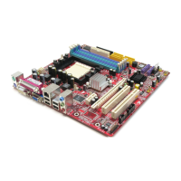
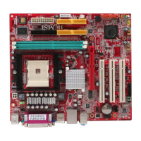
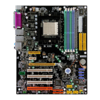
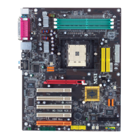
Specifies ATX form factor dimensions and mounting holes.

Rear Panel Connections

Hardware Setup Procedures

CPU Installation

Step-by-step guide for installing the CPU into Socket 754.

CPU Cooler Installation

System Overheating Warning

CPU Replacement and Memory Installation

DDR Module Installation

Power and Drive Connectors

IDE, SATA, Fan, and Audio Connectors

Optional Connectors and Front Panel Interfaces

CMOS, Expansion Slots, and Interrupts

BIOS Setup Guide

Main BIOS Menu Options

Lists primary BIOS configuration sections like CMOS, Chipset, and Power Management.

BIOS Default Settings Management

Options for loading optimal or high-performance default BIOS settings.

BIOS Cell Menu Details

Cool'n'Quiet and Spread Spectrum Settings

Configuration for CPU power saving and EMI reduction features.

PCI Slot Clock Control

Option to enable or disable the clock signal for unused PCI slots.

CPU Ratio and Dynamic Overclocking

FSB and DRAM Clock Configuration

Settings for CPU Front Side Bus and DRAM clock modes.
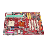
DRAM and AGP Voltage Tuning

Voltage Setting Precautions

Related product manuals