2-13
Hardware Setup
Fan Power Connector: CPUFAN1, SYSFAN1
The fan power connectors support system cooling fan with +12V. When connecting
the wire to the connectors, always note that the red wire is the positive and should
be connected to the +12V; the black wire is Ground and should be connected to GND.
If the mainboard has a System Hardware Monitor chipset onboard, you must use a
specially designed fan with speed sensor to take advantage of the CPU fan control.
SYSFAN1
SENSOR
+12V
GND
Important
1.Please refer to the recommended CPU fans at processor’s official website
or consult the vendors for proper CPU cooling fan.
2.CPUFAN1 supports fan control. You can activate the Smart Fan function in
the BIOS Setup Utility to automatically control the CPU fan speed according
to the actual CPU temperature.
3. Fan/heatsink with 3 or 4 pins are both available for CPUFAN1.
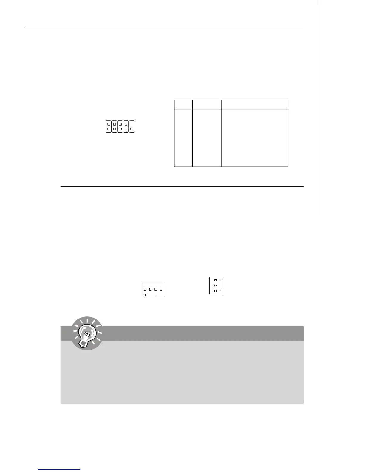
PIN SIGNAL DESCRIPTION
1 DCD Data Carry Detect
2 SIN Serial In or Receive Data
3 SOUT Serial Out or Transmit Data
4 DTR Data Terminal Ready
5 GND Ground
6 DSR Data Set Ready
7 RTS Request To Send
8 CTS Clear To Send
9 RI Ring Indicate
Pin Definition
JCOM1
1 9
2
Serial Port Connector: JCOM1
This connector is a 16550A high speed communications port that sends/receives 16
bytes FIFOs. You can attach a serial device to it.
CPUFAN1
S
E
N
S
O
R
+
1
2
V
G
N
D
C
O
N
T
R
O
L