2-13
Hardware Setup
Important
1.Please refer to the recommended CPU fans at AMD
®
official website or
consult the vendors for proper CPU cooling fan.
2.Always consult the vendors for proper CPU cooling fan.
3. Fan/heatsink with 3 or 4 pins are both available for CPUFAN1.
SYSFAN1
+12V
GND
SENSOR
CPUFAN1
Control
SENSOR +12V
GND
SYSFAN2
+12V
GND SENSOR
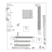
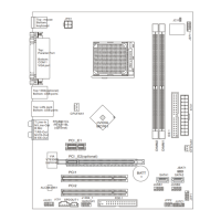
Fan Power Connectors: CPUFAN1, SYSFAN1, SYSFAN2
The fan power connectors support system cooling fan with +12V. When connecting
the wire to the connectors, always note that the red wire is the positive and should
be connected to the +12V; the black wire is Ground and should be connected to GND.
If the mainboard has a System Hardware Monitor chipset on-board, you must use a
specially designed fan with speed sensor to take advantage of the CPU fan control.
Front Panel Audio Connector: JAUD1
This connector allows you to connect the front panel audio and is compliant with
Intel
®
Front Panel I/O Connectivity Design Guide.
JAUD1
1
2
9
10
PIN SIGNAL DESCRIPTION
1 MIC_L Microphone - Left channel
2 GND Ground
3 MIC_R Microphone - Right channel
4 PRESENCE# Active low signal-signals BIOS that a High Definition Audio dongle
is connected to the analog header. PRESENCE# = 0 when a
High Definition Audio dongle is connected
5 LINE out_R Analog Port - Right channel
6 MIC_JD Jack detection return from front panel microphone JACK1
7 Front_JD Jack detection sense line from the High Definition Audio CODEC
jack detection resistor network
8 NC No control
9 LINE out_L Analog Port - Left channel
10 LINEout_JD Jack detection return from front panel JACK2
HD Audio Pin Definition
PDF created with pdfFactory Pro trial version www.pdffactory.com
 Loading...