2-13
Hardware Setup
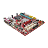
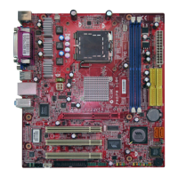
Fan Power Connectors: CPUFAN1, SYSFAN1
The fan power connectors support system cooling fan with +12V. When connecting
the wire to the connectors, always take note that the red wire is the positive and
should be connected to the +12V, the black wire is Ground and should be connected
to GND. If the mainboard has a System Hardware Monitor chipset on-board, you must
use a specially designed fan with speed sensor to take advantage of the CPU fan
control.
Important
Please refer to the recommended CPU fans at Intel
®
/ AMD
®
official website or
consult the vendors for proper CPU cooling fan.
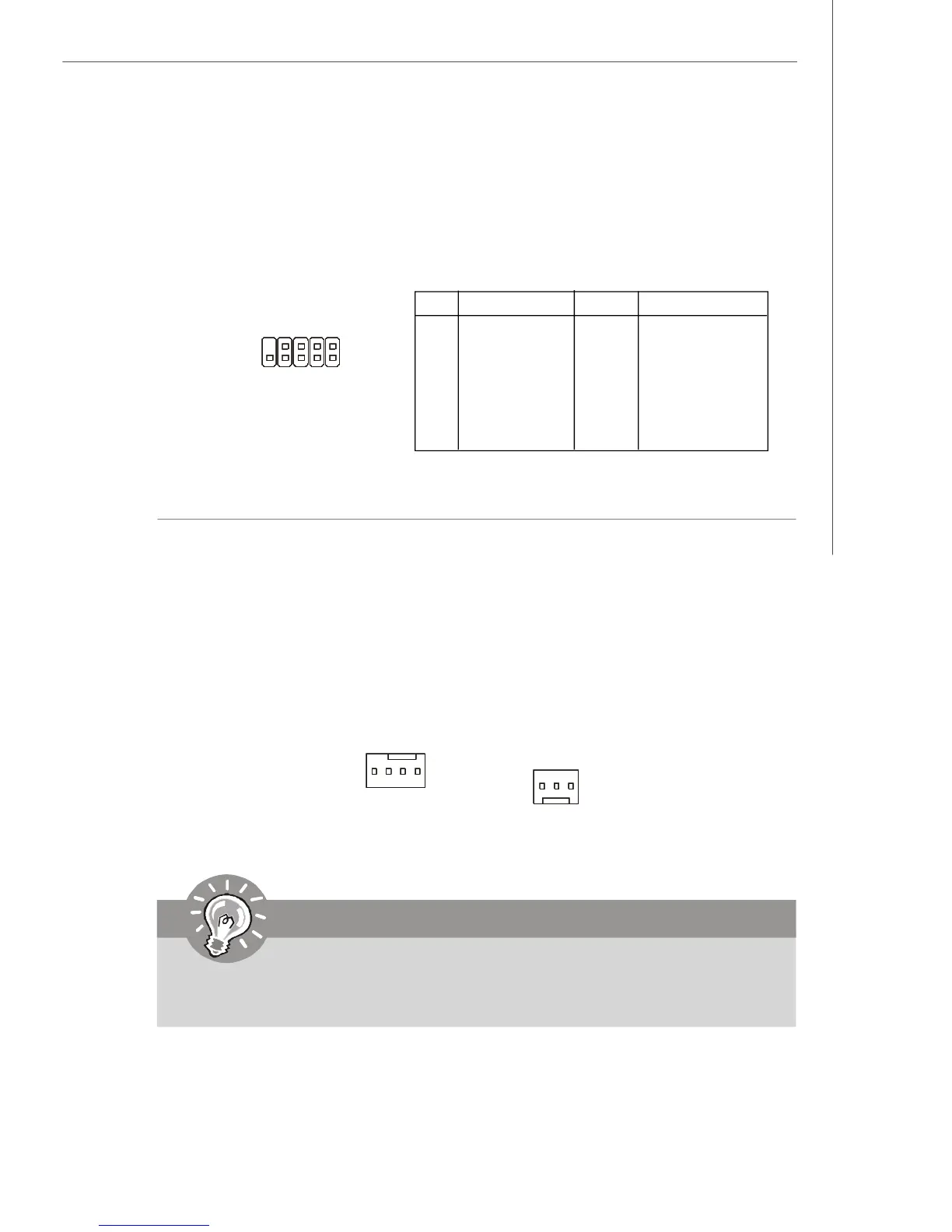
IEEE 1394 Connector: J1394_1 (Optional)
The mainboard provides an IEEE1394 pinheader that allows you to connect IEEE 1394
ports via an external IEEE1394 bracket (optional).
Pin Definition
PIN SIGNAL PIN SIGNAL
1 TPA+ 2 TPA-
3 Ground 4 Ground
5 TPB+ 6 TPB-
7 Cable power 8 Cable power
9 Key (no pin) 10 Ground
SYSFAN1
SENSOR
+12V
GND
J1394_1
1 9
2 10
CPUFAN1
SENSOR
+12V
GND
CONTROL