Fr-18
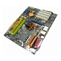
Carte mère MS-7514
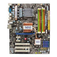
PIN SIGNAL DESCRIPTION
1 HD_LED + Hard disk LED pull-up
2 FP PWR/SLP MSG LED pull-up
3 HD_LED - Hard disk active LED
4 FP PWR/SLP MSG LED pull-up
5 RST_SW - Reset Switch low reference pull-down to GND
6 PWR_SW + Power Switch high reference pull-up
7 RST_SW + Reset Switch high reference pull-up
8 PWR_SW - Power Switch low reference pull-down to GND
9 RSVD_DNU Reserved. Do not use.
Définition des pins pour JFP1
Connecteurs du panneau avant : JFP1, JFP2
Ces connecteurs sont fournis pour la connecxion électrique aux interrupteuts et
LEDs du panneau avant. Le JFP1 est conforme au guide de conception de la
connectivité Entrée/sortie du panneau avant Intel
®
.
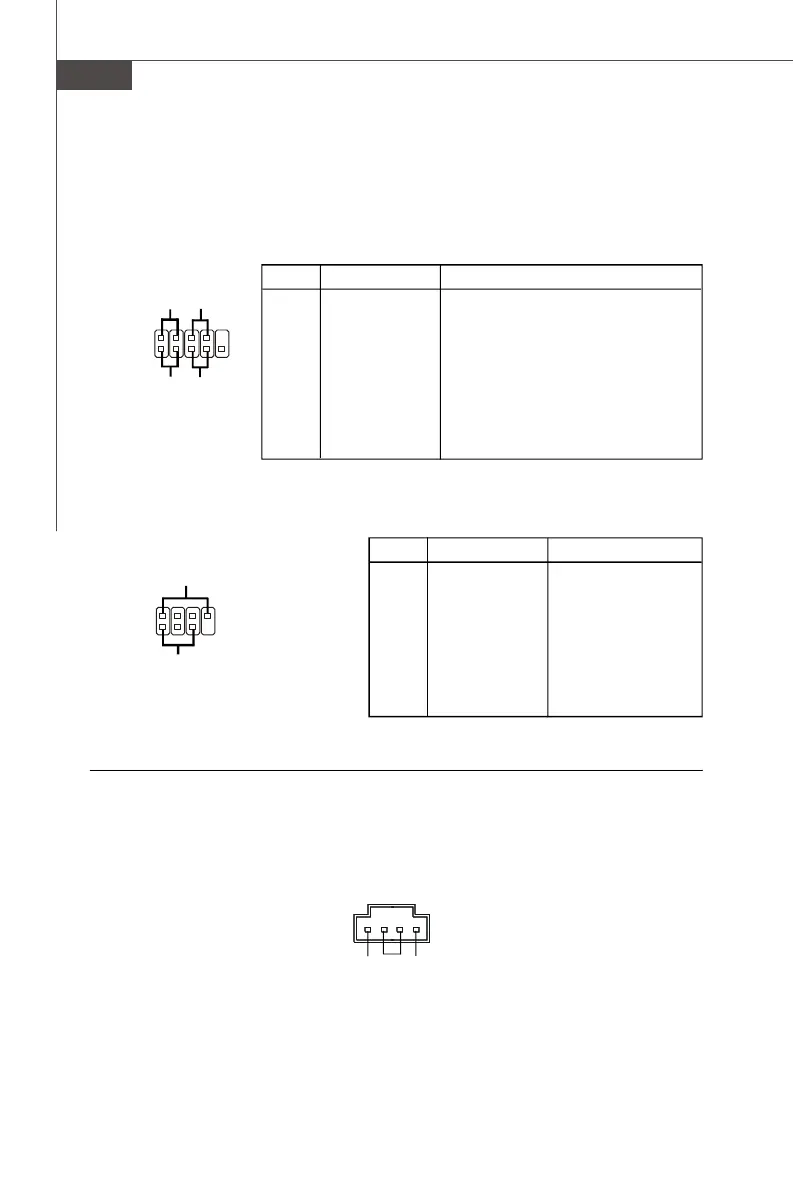
PIN SIGNAL DESCRIPTION
1 GND Ground
2 SPK- Speaker-
3 SLED Suspend LED
4 BUZ+ Buzzer+
5 PLED Power LED
6 BUZ- Buzzer-
7 NC No connection
8 SPK+ Speaker+
Définition de pins pour JFP2
1
2
9
10
JFP1
HDD
LED
Reset
Switch
Power
LED
Power
Switch
+
+
+
-
-
-
7
8
Power
LED
Speaker
1
2
JFP2
-
-
+
+
Connecteur CD-In : JCD1
Ce connecteur est fournit pour un audio externe d’entrer.
JCD1
GND
R
L
 Loading...