1-31
MS-7751
Chapter 1
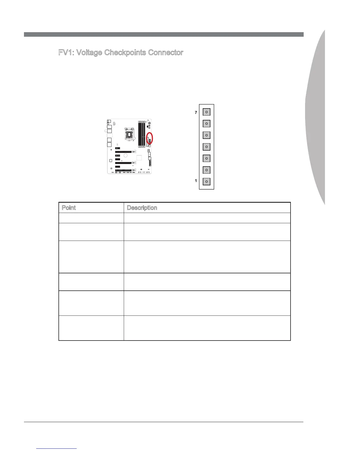
FV1: Voltage Checkponts Connector
These voltage checkpont are used to measure the current system voltages. A multmeter
(not ncluded) wll be requred to check voltages. To check the voltage, please use
the ncluded voltage checkpont cables ncluded n the manboard package. Attach the
postve lead of the multmeter to the voltage checkpont cable and the negatve lead to
the ground connector.
VCC_DDR
GND
1
7
PCH_1P05
CPU_GFX
CPU_VTT
VCCP
GND
Pont Descrpton
GND (pn 6, pn 7)
Ground
PCH_1P05 (pn 5) PCH 1.05 voltage. The PCH voltage s the voltage suppled
to the Platform Controller Hub.
VCC_DDR (pn 4) Memory voltage. The DDR memory voltage s the voltage
suppled to the DDR memory modules on the manboard.
Lower memory tmngs may requre hgher voltages to
mantan system stablty.
CPU_GFX (pn 3) The CPU_GFX voltage s the voltage suppled to the
ntegrated graphcs processor located on the CPU.
CPU_VTT (pn 2) CPU IO voltage (Uncore). The CPU IO voltage s the voltage
suppled to the Uncore on the CPU. Hgher overclocks may
requre a hgher CPU IO voltage to mantan stablty.
VCCP (pn 1) CPU core voltage. The CPU voltage s the voltage suppoed
to the CPU core. Hgher overclocks may requre hgher CPU
core voltages to mantan stablty.
 Loading...