EasyManua.ls Logo

MSR ELECTRONIC PolyGard 2 - Sensor Element

MSR ELECTRONIC PolyGard 2
15 pages
Print Icon
To Next Page IconTo Next Page
To Previous Page IconTo Previous Page
Loading...
User Manual - PolyGard
®
2 / µGard
®
2
Sensors for Toxic Gases
Page 12
PolyGard
/ µGard
®
are registered trademarks of MSR Made in Germany GA_SC2_MC2_Tox_D_0820
Phone +49 8531 9004-0 Fax: +49 8531 9004-54 Specification subject to change without notice
MSR-Electronic GmbH, Buergermeister-Schoenbauer-Str. 13, D 94060 Pocking www.msr-electronic.de
9.3 Sensor Element
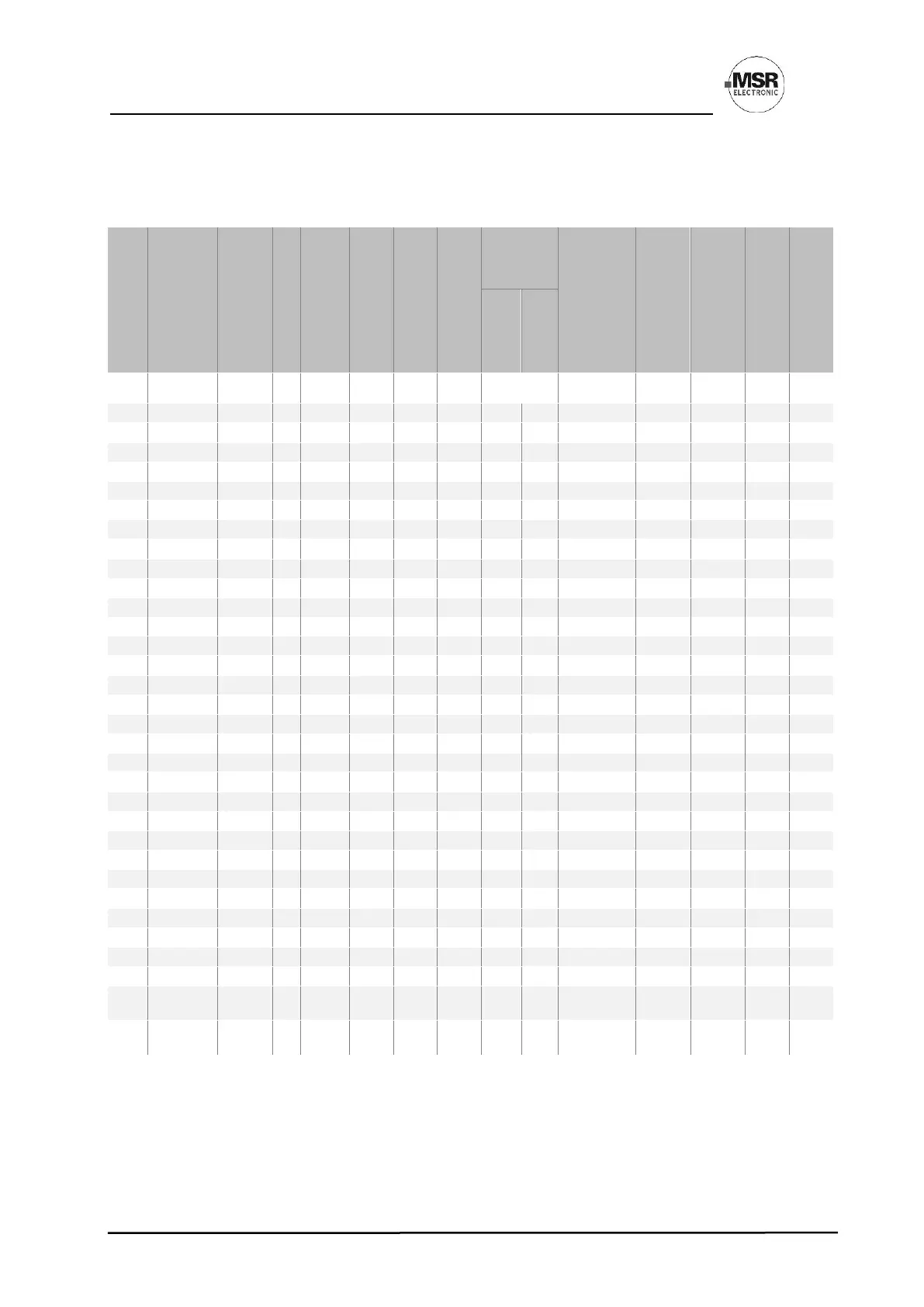
SPECIFICATIONS - Sensor Cartridge (SC2/MC2) / Sensor element
Gas type
Ordering
No.
Measuring range
Accuracy
Display resolution
Repeatability
t90 time
Zero-point variation
Drift in
air
Temperatur
e range
Humidity range
(non-
condensing
)
Life time
1
in air
Relative
Gas density
2
Calibration
interval
1
Zero
Gain
SC2-/MC2-
ppm
± %
sig.
ppm
%
sig.
≤ sec.
±ppm
< % signal/
month
°C
% r. F.
>
months
Air = 1
Month
NH
3
E1125-AX
0100
5
0.1
10
75
5
1
1
-30 / +50
1590
24
0.60
12
NH
3
E1125-BX
0300
3
0.1
10
75
5
1
2
-30 / +50
1590
24
0.60
12
NH
3
E1125-CX
0500
3
0.1
10
75
5
1
2
-30 / +50
1590
24
0.60
12
NH
3
E1125-DX
01000
3
1
10
75
10
1
2
-30 / +50
1590
24
0.60
12
NH
3
E1125-EX
05000
2
1
10
40
100
1
2
-30 / +50
1590
24
0.60
12
Cl
2
E1193-CX
010
n.d.
0.01
5
40
0.2
1
2
-30 / +50
1590
24
2.48
6
Cl
2
E1193-DX
020
n.d.
0.01
5
40
0.2
1
2
-30 / +50
1590
24
2.48
6
HCl
E1186-DX
020
5
0.01
5
60
0.5
1
2
-20 / +50
1590
24
1.27
6
HCN
E1183-BX
050
5
0.01
5
30
2
1
2
-20 / +50
1590
24
0.93
6
HCN
E1183-CX
0100
5
0.1
5
30
2
1
2
-20 / +50
1590
24
0.93
6
ETO
E1199-AX
010
n.d.
0.01
5
150
1
1
2
+10 / +30
1590
24
1.56
12
C
2
H
4
E1189-CX
0200
n.d.
0.1
5
120
5
2
5
-30 / +50
1590
24
0.97
6
CH
2
O
E1185-BX
010
n.d.
0.01
5
60
0.2
1
2
-30 / +50
1590
36
1.04
6
CO
E1110-CX
0150
2
0.1
5
10
4
0.4
0.4
-20 / +50
1095
72
0.97
12
CO
E1110-EX
0250
2
0.1
5
10
4
0.4
0.4
-20 / +50
1095
72
0.97
12
CO
E1110-FX
0300
2
0.1
5
10
4
0.4
0.4
-20 / +50
1095
72
0.97
12
CO
E1110-HX
0500
2
0.1
5
10
4
0.4
0.4
-20 / +50
1095
72
0.97
12
O
3
E1190-AX
05
n.d.
0.001
5
60
0.1
1
2
-30 / +50
1590
24
1.66
6
O
3
E1190-BX
010
n.d.
0.01
5
60
0.2
1
2
-30 / +50
1590
24
1.66
6
SO
2
E1196-BX
020
3
0.01
5
30
0.2
1
2
-20 / +50
1590
24
2.73
6
H
2
S
E1197-AX
050
3
0.01
5
30
1
1
2
-10 / +50
1590
24
1.19
12
H
2
S
E1197-BX
0100
3
0.1
5
40
1
1
2
-10 / +50
1590
24
1.19
12
H
2
S
E1197-CX
0200
3
0.1
5
40
2
1
2
-10 / +50
1590
24
1.19
12
H
2
S
E1197-DX
0500
3
0.1
5
40
5
1
2
-10 / +50
1590
24
1.19
12
H
2
S
E1197-EX
01500
3
1
5
60
15
n.d.
n.d.
-10 / +50
1590
24
1.19
12
NO
2
E1130-AX
010
5
0.01
2
25
0.2
1
2
-30 / +50
1590
24
2.80
12
NO
2
E1130-BX
020
5
0.01
2
25
0.2
1
2
-30 / +50
1590
24
2.80
12
NO
2
E1130-CX
030
5
0.01
2
25
0.2
1
2
-30 / +50
1590
24
2.80
12
NO
2
E1130-EX
0100
5
0.1
2
25
2
1
2
-30 / +50
1590
24
2.80
12
Vol %
O
2
E1195-
A2/3
025
2
0.01
n.d.
15
n.d.
n.d.
0.4/
0.6
-40 / +50
595
24/36
1.11
6/6
O
2
E1195-
A5/7
025
2
0.01
n.d.
15
n.d.
n.d.
0.4
-40 / +50
1590
60/84
1.11
12/12
1
Manufacturer-recommended calibration interval for normal environmental conditions
2
The sensor must be installed at the correct height depending on the relative gas density (d):
d < 0.95: Mount on the ceiling
0.95 < d < 1.05: Mount at a height of 1.51.8 m above floor
d > 1.05: Mount at a height of 0.3 m above floor
Exception NO
2
: Mounting height for NO
2
sensors: 0.5 to 1.8 m above floor!
3
Exceeding the measuring range limit will include a risk of damaging the sensor element.

Related product manuals