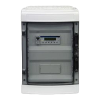
The PolyGard®2 DGC6 Digital Gas-Controller-Series GC-06 Modbus is a gas controller designed for monitoring and managing gas levels, with Modbus RTU serial interface capabilities for integration into larger control systems. This supplement focuses on the Modbus communication aspects, enabling external systems to read data from and send commands to the DGC6 controller.
Function Description
The DGC6 Modbus supplement outlines how external Modbus master controllers can interact with the DGC6 gas controller, which acts as a Modbus slave. The primary function is to allow reading of various sensor data, alarm statuses, relay statuses, and error codes from the DGC6 system. Additionally, it supports writing single coils or registers for specific control actions such as acknowledging alarms or activating watch outputs.
Modbus Function 03 (Reading of Registers): This function is used to retrieve data from the DGC6 system. It allows reading of:
- Current values of digital sensors: For sensor addresses 1–96, data is available in Modbus registers 1001–1096.
- Current values of analog sensors: For sensor addresses 1–32, data is available in Modbus registers 2001–2032.
- Average values of digital sensors: For sensor addresses 1–96, data is available in Modbus registers 3001–3096.
- Average values of analog sensors: For sensor addresses 1–32, data is available in Modbus registers 4001–4032.
- Measuring range of digital sensors: For sensor addresses 1–96, data is available in Modbus registers 5001–5096.
- Measuring range of analog sensors: For sensor addresses 1–32, data is available in Modbus registers 6001–6032.
- Alarms and latching bits of digital sensors: Local alarms and latching bits for digital sensors (1–96) are displayed in Modbus registers 1201–1296. The data is presented in hexadecimal form, with 4 status bits for each of the 4 alarm stages. A value of '1' indicates an active alarm or latching, while '0' indicates inactivity.
- Alarms and latching bits of analog sensors: Local alarms and latching bits for analog sensors (1–32) are displayed in Modbus registers 2201–2232, also in hexadecimal format with 4 status bits per alarm stage.
- Relay status of signal relays: For signal relay addresses 1–96, status is available in Modbus registers 7001–7096.
- Relay status of alarm relays: For alarm relay addresses 1–32, status is available in Modbus registers 8001–8032. The controller's fault message relay status is in register 8000, with values: -1 (not active), 0 (active, not energized), and 1 (active, energized).
- Error codes: Modbus registers 9000–9104 provide error codes. Register 9000d indicates local errors of the connected GC device, such as MP errors (0x0100) or EEPROM/configuration errors (0x0010). Registers 9001d–9096d show local errors of connected devices like WSB2, SB2, or MSB2. Registers 9097d–9104d indicate local errors of the 8 Gas Controller Modules (1x GC06 + 7x EP06), with 0x8100 signifying an MP error. Error codes are broken down into nibbles, each with 4 bits (8, 4, 2, 1) representing different error types (e.g., error indicator, special mode ON, UPS detected, maintenance information, configuration error, power failure, UPS error, horn, feedback error, wrong analog output current, over/undervoltage, AD converter failure).
- DGC-06 Watch Outputs (WI): Modbus registers 50–57 display watch outputs. Register 50 shows all watch outputs as a byte, while registers 51–57 provide individual bit values as Integer values. Output states can be: 0 (no output set), 1 (switch on by clock), 256 (switch on by Modbus), or 257 (switch on by Modbus and clock).
- Data block: Output: This block provides information about the Modbus slave address (Address 0), relay information bits for the first module (Controller Module) and extension modules (Addresses 1-8), and hardware analog outputs (Addresses 9-24).
Modbus-Function 05 (Write Single Coil): This function allows writing single states (ON/OFF) to acknowledge latching modes or horns, and to set clock outputs individually.
- Acknowledgement of latching mode: Command 05 is sent to the DGC-06 address with an indication of the respective chapter (3.7 or 3.8). Acknowledgment occurs when the value ON (0xFF00) is sent.
- Acknowledgement of horn: Command 05 is sent to the DGC-06 address and register 0x7000. Acknowledgment occurs when the value ON (0xFF00) is sent.
- Activation of the single Watch Output via Modbus: Command 05 is sent to the DGC-06 address with an indication of the respective chapter 3.12, but register 50 is not allowed for this operation.
Modbus Function 06 (Write Single Registers): This function is used to write to individual registers in the DGC-06. Currently, it only supports writing to the device's own slave address (Modbus address 0, see chapter 3.12).
Modbus-Function 15 (Write Multiple Coils): This function allows setting multiple watch outputs (OFF/ON) simultaneously. The command must be sent to the DGC-06 address with the indication of register 50, with a maximum length of 7 bits.
Modbus Function 16 (Write Multiple Registers): This function is used to write to several registers in the DGC-06. Similar to Function 06, it currently only supports writing to the device's own slave address (Modbus address 0, see chapter 3.12). For safety reasons, other parameter changes are not permitted, ensuring data flow is strictly from the warning system to the Modbus side, without retroaction.
Important Technical Specifications
- Serial Modbus Interface: The DGC6 uses a Modbus RTU serial interface at the X-BUS. This functionality is available from display version 1.00.06 onwards.
- Communication Parameters:
- Baud rate: 19,200 baud
- Data bits: 8
- Stop bits: 1
- Parity: Even
- Modbus Role: The DGC6 gas controller operates as a Modbus slave.
- Modbus Master Controller Requirements: The Modbus master controller must have a resistor matrix at the fieldbus terminals to maintain a voltage level of at least 0.5 V at bus pin A when the driver is inactive. This resistor circuitry is typically integrated into Modbus master controllers.
- Measured Value Representation: Measured values are shown in Integer format with a factor that depends on the measuring range:
- 1-9: Factor 1000
- 10-99: Factor 100
- 100-999: Factor 10
- Ab 1000: Factor 1
- Values below -16385 indicate an error message and should be interpreted as a hexadecimal value to break down the errors.
- Hardware Analog Output: Addresses 9 to 24 correspond to hardware analog outputs 1 to 16. Values are defined between 0 and 10000 (representing the full-scale value of the sensor).
Usage Features
- Remote Monitoring: The Modbus interface enables remote monitoring of gas levels, alarm statuses, and device health from a central control system.
- Alarm Management: Operators can remotely acknowledge latching alarms and horn signals via Modbus commands, streamlining alarm management processes.
- Watch Output Control: Individual watch outputs can be activated via Modbus, offering flexible control over connected devices or indicators. Multiple watch outputs can also be set simultaneously.
- Diagnostic Capabilities: Access to error codes provides detailed diagnostic information, allowing for quicker troubleshooting and maintenance planning.
- Integration: The Modbus RTU protocol ensures compatibility with a wide range of industrial control systems and building management systems.
Maintenance Features
- Regular Inspection: It is recommended that PolyGard®2/PolyXeta®2 equipment be inspected regularly to ensure optimal performance.
- Recalibration and Parts Replacement: Performance deviations can be corrected through regular maintenance, including recalibration and parts replacement by a qualified technician using appropriate tools.
- Sensor Head Service: The easily removable, plug-in sensor head can be returned to INTEC Controls | MSR-Electronic GmbH for service, simplifying maintenance procedures.
- Adherence to Instructions: Regular maintenance must be carried out according to the provided instructions to ensure the product functions as intended and to maintain warranty validity.
- Warranty: INTEC Controls | MSR-Electronic GmbH offers a 2-year warranty on PolyGard®2/PolyXeta®2 devices (1 year for sensors) against defects in material or workmanship. This warranty is contingent on proper installation, use, maintenance, and repair according to instructions.
- Disposal: The device must be disposed of in accordance with Directive 2012/19/EU, meaning it should not be treated as municipal waste. It should be returned to the national sales organization for proper disposal.

 Need help?
 General

 To Next Page
