QM7500 Technical Manual
12 Servicing QM31930/03093 Rev AD
Note: Hold the components in place with your finger if necessary. Make
sure the valve/photocell board assembly remains in the printhead base.
Also, avoid unnecessary flexing of the cable between the two boards to
prevent damaging the cable connections.
3) Carefully lift the controller mounting frame off the bottom half of the
printhead.
4) Carefully slide up the photocell board.
5) Slide out the nozzle block.
Installing the New Nozzle Block
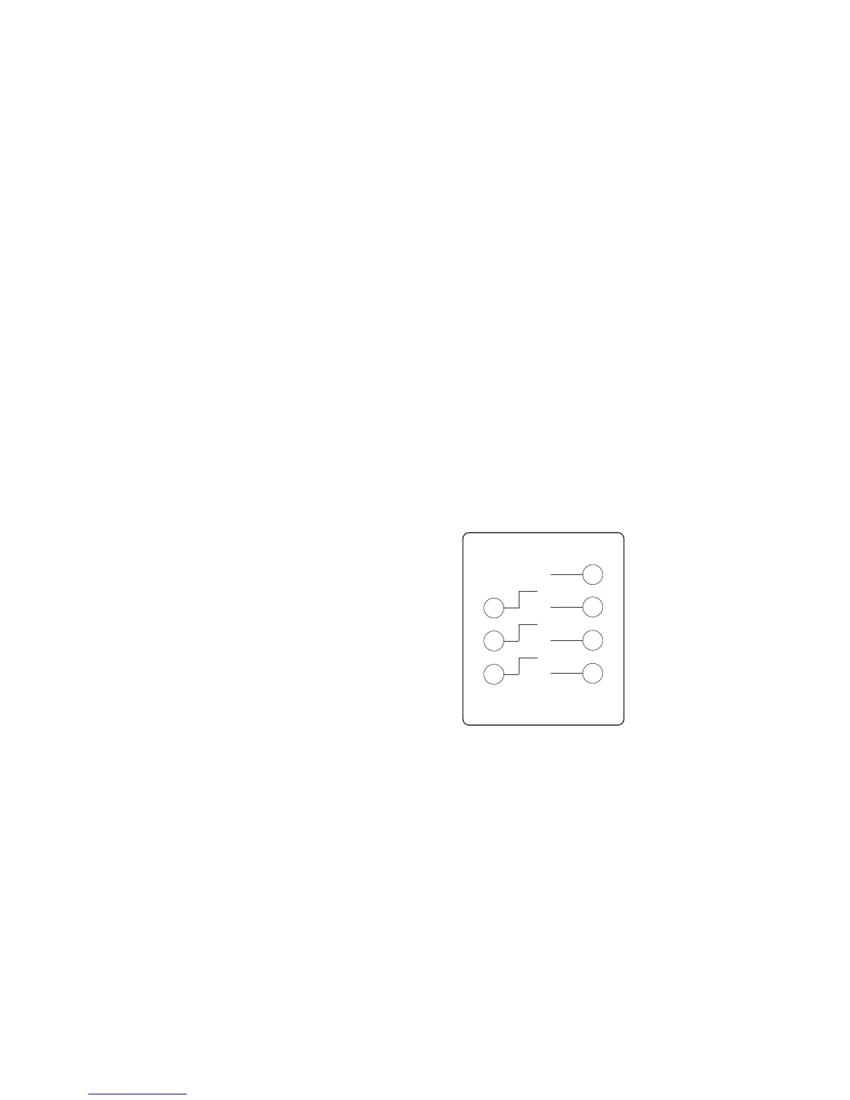
1) Pull off the ink tubes one at a time. As you disconnect an ink tube from the old
nozzle block, connect it to the corresponding nozzle of the replacement nozzle
block. (See Figure B.)
2) Slide the newly connected nozzle block into its slot in the printhead.
3) Replace the photocell board and printhead cover. Be careful not to pinch any
of the wires in the printhead.
4) Install an ink bottle, plug the system in, and purge the QM7500 with ink to
remove any air introduced into the system.
Your unit is ready to return to normal operation.
Figure B: Valve Board to Nozzle Block Diagram
Optional 7 mm, 15 mm, and 20 mm Nozzle Blocks
An optional 7 mm, 15 mm and 20 mm nozzle block is available for the QM7500
printhead. If you wish to install a 7 mm, 15 mm or 20 mm nozzle block, see the
Parts List section of this manual for ordering information and follow the procedure
for replacing the nozzle block.
Replacing a Valve
Removing the Valve
1) Prepare your QM7500 for servicing. (See page 6.)
Valve Valve
1
2
3
4
5
6
7
2
1
3
5
7
4
6
Nozzle
Block
Front View