TAEevo M05-M10
13
MAINTENANCE AND OPERATING MANUAL
The data inside this manual are not binding and they can be modified by the manufacturer without notice. All rights reserved.
7.7 Alarms signalling
The “P1” and “P2” probe alarms trip few seconds after the probe develops a fault; they switch off automatically few seconds after the probe
starts to function properly. Before renewing the probe check the connections.
The “HA” and “LA” temperature alarms switch off automatically as soon as the thermostat temperature returns to normal.
The external EA and CA alarms switch off as soon as the digital input is deactivated.
If the I.D. is configured as a pressure switch (i1F=bAL) the reset is performed manually by switching off the instrument.
7.8 Unit general parameters
The unit is factory-equipped with preset parameters, which are values calculated for standard applications. If it becomes necessary to edit the
values of any of the general parameters, we recommend contacting your Service Centre.
Failure to observe this prescription exposes the user and unit to potential risks.
ATTENTION
The manufacturer declines all possible warranty claims concerning performances and safety standards following arbitrary modification of the
parameters by the user.
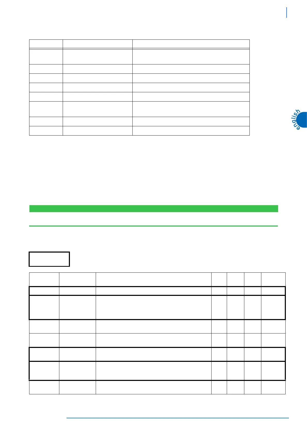
7.8.1 Control parameters
Message Cause Outputs
P1 Thermostat probe (-BT1) faulty Compressor output according to parameters “COn” and “COF”
(alarm relay changeover)
P2 Evaporator probe faulty Defrost by time (function not active)
HA High temperature alarm Not modified (alarm relay changeover)
LA Low temperature alarm Not modified (function not active, alarm relay changeover)
EA External alarm Not modified (alarm relay changeover)
CA High pressure switch alarm (HP)
(i1F=bAL)
Loads off (alarm relay changeover)
dA Door open Loads according to “odC” (alarm relay changeover)
CA Pressure switch alarm (i1F=PAL) Loads off (alarm relay changeover)
Visible parameters The visible parameters are set during the design stage. If it becomes necessary to make a hidden parameter visible,
follow the procedure described in chapter 7.2.2 “MEANING OF LEDs”
Parameter Description Min. Max. U.M.
Factory
settings
Set Set-point The setting for water temperature at the unit outlet -50 110 °C 7
Hy
Hysteresis Set-point trip differential. The hysteresis value is added to the
set-point: the relay is energised when the temperature reaches
the set-point + hysteresis value and de-energised when the
temperature returns to the set-point value.
0,1 25 °C 4
LS
Minimum set-
point value
Establishes the set-point minimum value.
-50 SET °C 0
US
Maximum set-
point value
Establishes the set-point maximum value.
SET 110 °C 30
Ot
Thermostat probe
calibration
Serves to calibrate the thermostat probe
-12 12 °C 0
P2P
Evaporator probe
presence
Serves to set the evaporator probe:
n= not present
Y= present.
n
OE
Evaporator probe
calibration
Serves to calibrate the evaporator probe
-12 12 °C 0
Table 4 C
ONTROL
PARAMETERS
 Loading...