24
MAINTENANCE AND OPERATING MANUAL
Chapter 7 - Electronic Board
The data inside this manual are not binding and they can be modified by the manufacturer without notice. All rights reserved.
TAEevo015÷351
7.2.1 Function of combined buttons
7.3 Symbols and leds on the display
7.4 Remote terminal
7.4.1 Function of buttons
If there is no communication between the unit and the remote terminal, in the top part of the
display it appears the message “
OP-
” (no link).
NOTE
The displaying depends on the setting of parameter CF43-CF44 (see chapter 7.9 “
Values displayed”
).
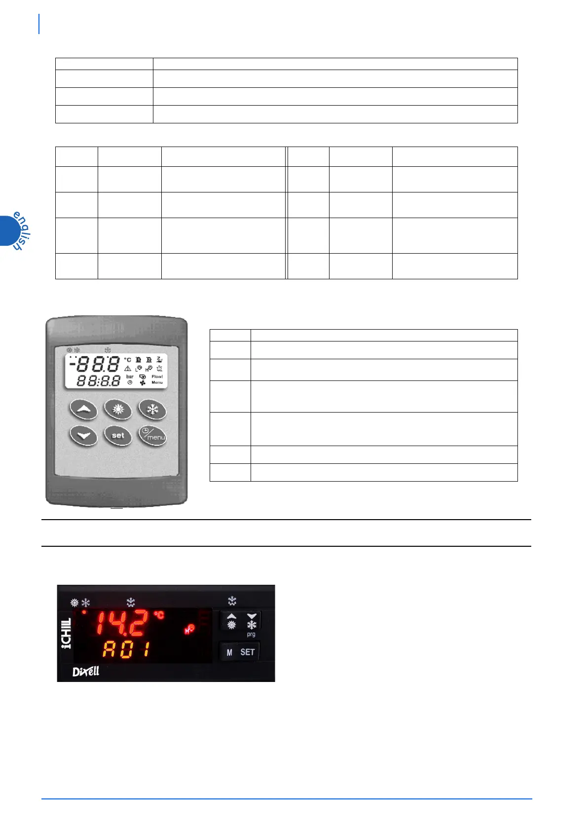
7.5 Displaying during an alarm
BUTTONS FUNCTION
&
+
-
To enter programming phase (pressed for 5 sec).
)
+
-
To exit programming phase.
)
+
-
If pressed for more than 5 seconds they allow to start a manual defrosting cycle (function not present).
LED LED STATUS MEANING LED LED STATUS MEANING
4
Not enabled
5
Not enabled
Steady Unit on in chiller modality
5
Not enabled
5
Flashing
Programming phase (if flashes
together with
led)
Clock adjustment
5
Not enabled
BUTTON FUNCTION
0
It allows to enter Function Menu.
2
If pressed for 5 sec., it allows to display or modify the set point.
During programming phase it selects a parameter or confirms a value.
1
It selects water temperature in the top part of the display.
During programming phase it scrolls the parameter’s codes or increases their
values.
3
It selects water temperature in the top part of the display.
During programming phase it scrolls the parameter’s codes or decreases their
values.
/
If pressed for 5 seconds it allows to switch on or off the unit.
.
Not enabled
During normal operation (no alarm), when an alarm occurs the alarm
code and the appropriate icon flash in the bottom part of the display,
alternated to the temperature / pressure.