TAEevo015÷351
29
MAINTENANCE AND OPERATING MANUAL
Chapter 8 - Other components setting
The data inside this manual are not binding and they can be modified by the manufacturer without notice. All rights reserved.
TAEevo015÷351
C
HAPTER
8
O
THER
COMPONENTS
SETTING
8.1 Compressor integral protection (PI)
For each compressor, this protection consists of three or six thermistor probes, each inserted in the winding of a motor phase; they are connected
in series and, depending on the model, the terminals can be external. This system ensures complete protection against most of the problems
which can give rise to burning of the windings. When it trips, it is necessary to find and eliminate the cause; then you can start the machine again
by pressing ON-OFF button.
8.2 Refrigerant high and low pressure switches
The units are fitted with the following pressure switches:
1. low pressure switch (LP)
This monitors refrigerant compressor suction pressure and will trip to avoid that values dangerous for compressor normal operation
are reached. It is of an “automatic reset” type. The alarm A02 (see chapter "12.1 Alarm codes and actions"), produced by this
pressure switch tripping, can have a delay time after the compressor starting to avoid simple intake pressure fluctuations or false
alarms interfere with the unit normal operation. After the time set, the pressure switch tripping will be detected by the electronic
board which will display the alarm signal A02 (see chapter "12.1 Alarm codes and actions") band will stop the compressor/s while
the pump (if it is installed) will continue to operate. After the alarm tripping, if the compressor intake pressure increases and exceeds
the pressure switch tripping value it will restart. It will be possible to start up the unit again following the alarm reset procedure
described in Chapter 7 “
Electronic Board”
. If the cause of the pressure switch tripping has not removed this cycle will repeat
continuously.
2. high pressure switch (HP)
This monitors the refrigerant compressor discharge pressure and prevents it increases to levels dangerous for compressor working
and for people safety. It is of an “automatic reset” type. Its tripping is detected by the electronic board which will open the
compressor power supply circuit and will display the alarm signal A01 (see chapter "12.1 Alarm codes and actions").
When the compressor outlet pressure drops below the reset point it is reset.
It will be possible to start up the unit again following the alarm reset procedure described in Chapter 7 “
Electronic Board”
.
If the cause of the pressure switch tripping has not removed this cycle will repeat continuously.
The pressure switches LP and HP are screwed to the refrigerant circuit piping with SCHRAEDER valves (with needle) which prevent leakage
during replacement.
The TRIP and RESET values of the pressure switches depend upon the refrigerant gas used and are listed in the table below:
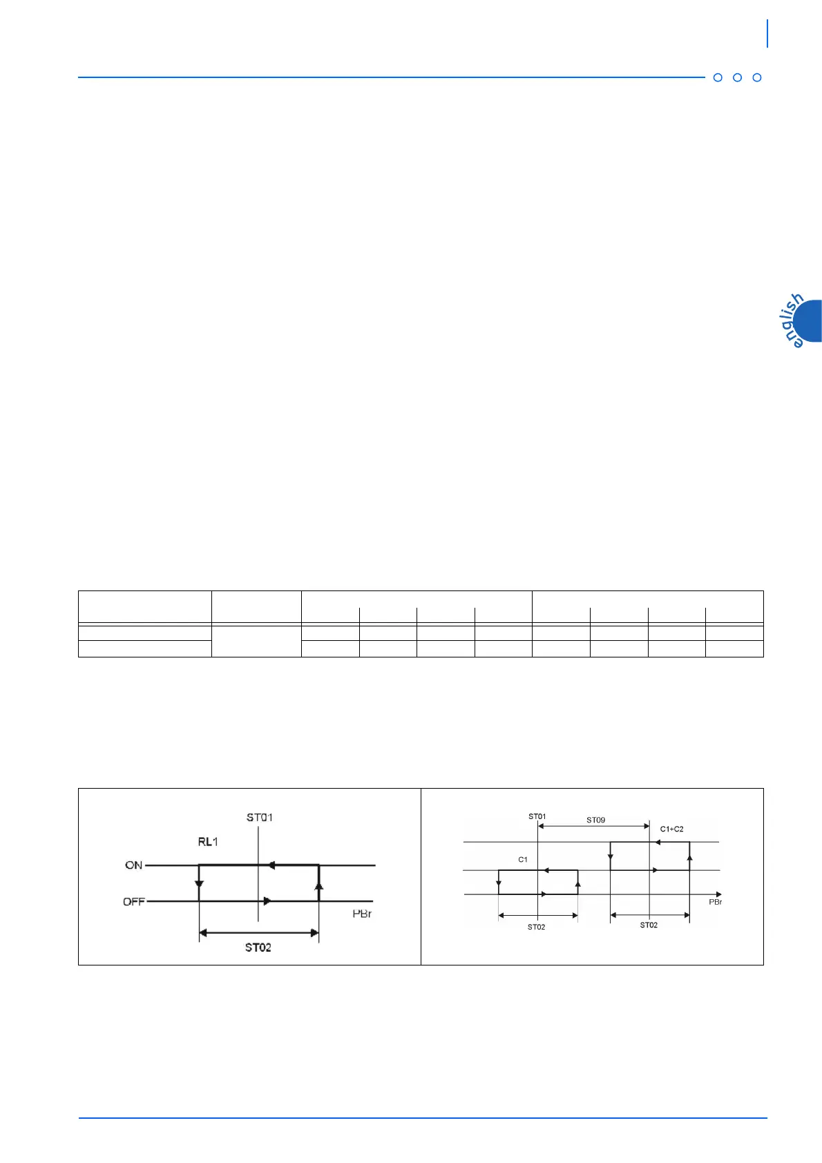
8.3 Compressor operation
The thermoregulation used is of proportional type. After fixing the temperature and differential values, the compressor will start when the value
measured will exceed the sum of temperature + differential. It will stop when the value will be lower than the temperature - differential. The
same logic will be applied also in two compressor units.
8.3.1 Compressor regulation graphic in Chiller mode
Pressure switch Refrigerant
TRIP RESET
bar PSI °C °F bar PSI °C °F
HP
R407C
27.2 394.5 63.4 146.1 20.5 297.3 51.5 124.7
LP 1.7 24.6 -17.3 0.9 2.7 39.1 -8.8 16.2
With 1 compressor With 2 compressors
ST09 = 2