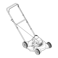
Yourmowerisshipped
withthehandleinthe
higherheightposition.
NOTE:Eachendof
thelowerhandlemust
beplacedinthesame
relativeposition.
IMPORTANT
I
i This unit is shipped
WITHOUT GASOLINE
or OiL. After assem-
bly, service engine
with gasolineand
oil as instructed in
I the separate engine
manual packedwith
your unit.
==,
_ ARNING" Disconnectand
ground the spark plug wire as
instructedinthe separate engine
manual.
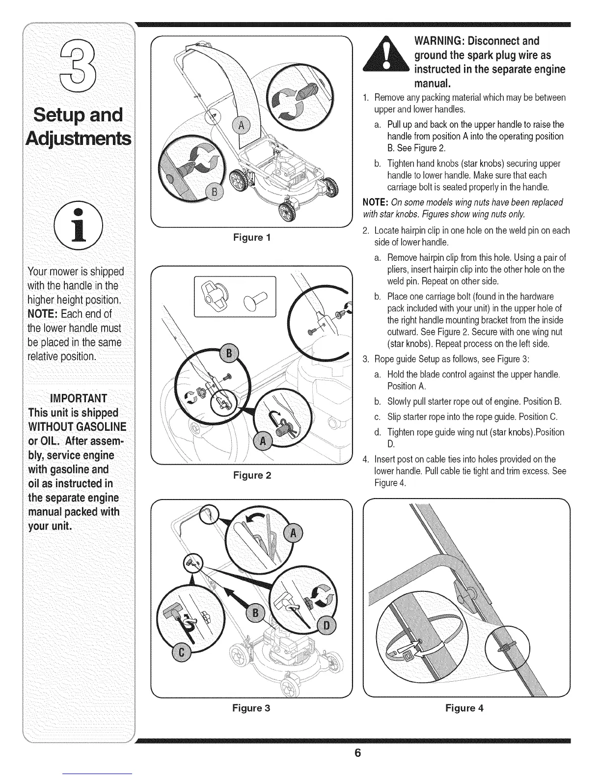
1. Removeanypackingmaterialwhichmaybebetween
upperandlowerhandles.
a. Pullupand backonthe upperhandleto raisethe
handlefrompositionA intothe operatingposition
B.SeeFigure2.
b. Tightenhandknobs(starknobs)securingupper
handletolowerhandle.Makesurethateach
carriagebolt is seatedproperlyin the handle.
NOTE:Onsomemodelswingnutshavebeenreplaced
withstarknobs.Figuresshowwingnutsonly.
2. Locatehairpinclipinone holeon the weldpinon each
sideof lowerhandle.
Figure 2
.
.
a. Removehairpinclipfromthis hole.Usinga pairof
pliers,inserthairpinclipintotheotherholeon the
weldpin.Repeaton otherside.
b. Placeonecarriagebolt (foundinthe hardware
packincludedwithyourunit) inthe upperholeof
therighthandlemountingbracketfromthe inside
outward.SeeFigure2. Securewithonewingnut
(starknobs).Repeatprocessonthe left side.
RopeguideSetupas follows,see Figure3:
a. Holdthebladecontrolagainstthe upperhandle.
PositionA.
b. Slowlypullstarterropeoutof engine.PositionB.
c. Slipstarterropeintotheropeguide.PositionC.
d. Tightenropeguidewingnut(starknobs).Position
D.
Insertpostoncabletiesintoholesprovidedon the
lowerhandle.Pullcabletie tightandtrimexcess.See
Figure4.
Figure 3 Figure 4
6