6
NOTE: The upper hole in the control handle provides
for adjustment in belt and cable tension. Refer to page
9 of this manual for instructions.
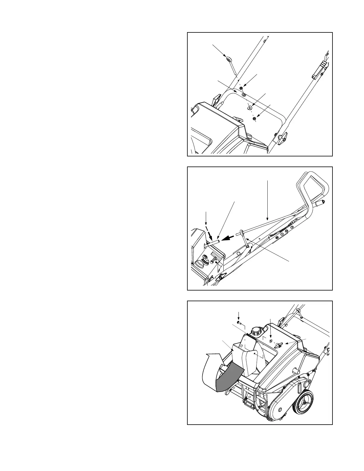
Installing the Chute Directional Control’s
Eye Bolt
(on models so equipped)
To install the upper crank of the chute directional
control, proceed as follows:
• Thread one of the hex nuts (they are
interchangeable) included in the snow thrower’s
hardware pack all the way onto the eye bolt.
• Insert the eye bolt into the hole found in the lower
handle’s crossbar. See Figure 4.
• Fasten the eye bolt to the crossbar with the saddle
washer (cupped side UP) and the other hex nut as
illustrated in Figure 4. Do NOT tighten at this time.
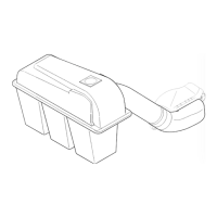
Installing the Extended Chute
Directional Control
(on models so equipped)
• Insert the chute directional control through the
eyebolt and into the coupler found in the top right
area of the snow thrower’s shroud. See Figure 5.
• Rotate the chute directional control to align the hole
in the coupler with the hole in the chute directional
control, and insert the cotter pin through both holes.
Bend the ends of cotter pin in opposite directions to
secure it in place. See Figure 5.
• Thread the eye bolt’s lower hex nut upward or
downward to adjust the height of the eye bolt so
that the chute directional control does not bind in
the coupler when operated.
• Fininsh by threading the upper hex nut downward
against the crossbar and tightening securely.
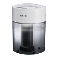
Assembling the Discharge Chute
For shipping reasons, the snow thrower has been
packaged with the upper chute pivoted all the way
down. To pivot it upward, proceed as follows:
• Turn the chute directional control until the chute
opening is facing straight ahead.
• Remove the wing knob, flat washer and carriage
bolt from the upper chute. See Figure 6.
• Pivot the upper chute upward over the lip on the
lower chute so that there is NO gap between the
upper chute and the lower chute. See Figure 6.
• Resecure with the hardware just removed.
Figure 4
Figure 5
Figure 6
Cotter Pin
Chute Directional Control
Coupler
Eye Bolt
Upper Chute
Wing
Knob
Flat
Washer
Carriage Bolt
Front
Lower Chute Lip
Eye Bolt
Hex Nut
Hex Nut
Saddle Washer
Cross Bar