5
SECTION 2: ASSEMBLING YOUR SNOW THROWER
NOTE: This Operator’s Manual covers several models.
Snow thrower features vary by model. Not all
features discussed in this manual are applicable to all
snow thrower models.
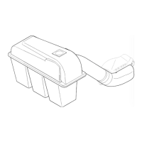
Contents of Carton
Before beginning installation, remove all parts from the
carton and compare them to Figure 1. Carton contents
are listed below with part numbers in parentheses.
•Two
Ignition Keys (725-0201, 725-1341B
†
)
† An ignition key with a plastic cover is included with
select models only. Two standard ignition keys are
included with all other models.
On Models So Equipped:
• Extended Chute Directional Control Assembly
(747-0737, 720-0201A & 726-0100)
• One Cotter Pin (714-0507)
• One Saddle Washer (736-0415)
• Two Hex Nuts (712-3010)
• One Eye Bolt (747-0697) w/ Grommet (735-0234)
Figure 1
NOTE: All references to left or right side of the snow
thrower is from the operating position only.
WARNING: Disconnect the spark plug wire
and ground it against the engine to prevent
unintended starting.
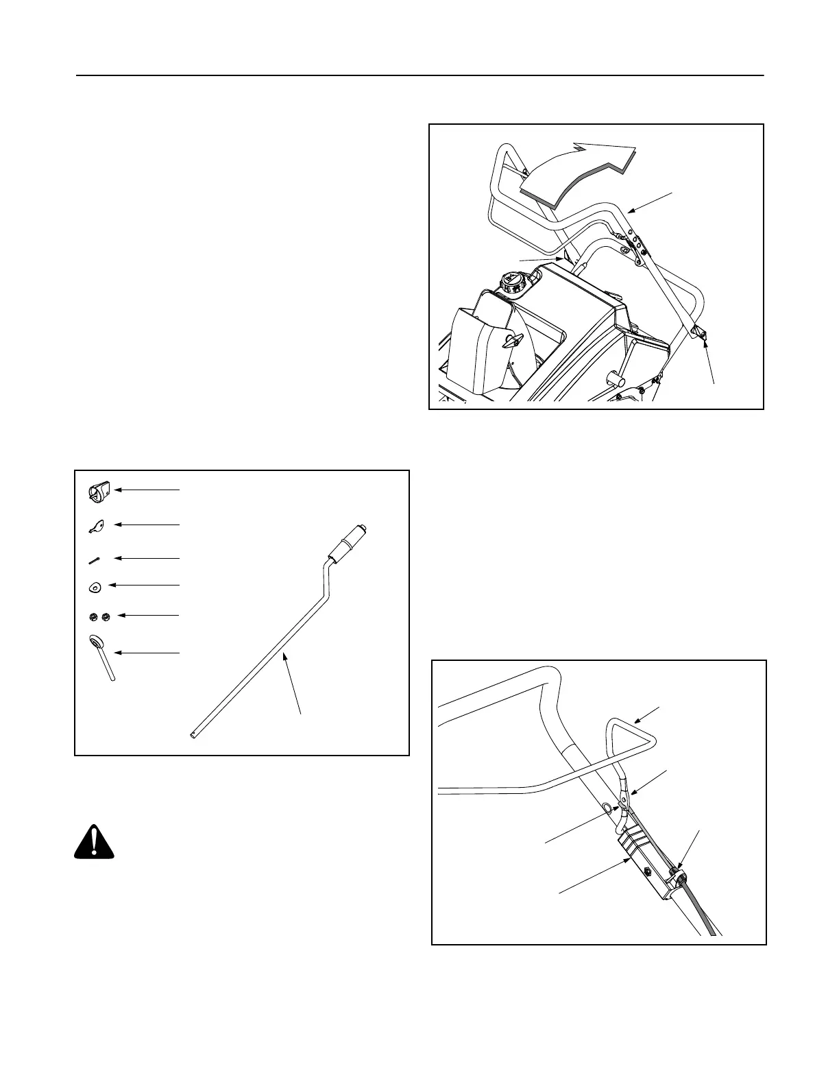
Positioning the Upper Handle
• Remove packing material, if present, and loosen
the wing knobs found on each side of the handle.
• Making sure not to pinch or crimp the cable in the
process, pivot the upper handle into the operating
position as illustrated in Figure 2 until it clicks into
place.
Figure 2
• Tighten the wing knobs to secure the handle in
place.
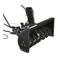
Attaching the Control Cable
The control cable may already be attached to the
control handle. If it’s not, complete the following steps
to attach it to the snow thrower housing.
• Route the control cable over the crossbar where
the lower handle meets the upper handle.
• Pivot the control handle forward and insert the end
of the control cable into the bottom hole in the
control handle, from the outside to the inside, as
shown in Figure 3.
Figure 3
• Push the plastic fitting into the control housing until
it clicks in place
Ignition Key w/ Plastic Cover
†
Standard Ignition Key
Cotter Pin
Extended Chute
Directional Control Assembly
Eye Bolt
Saddle Washer
Hex Nuts
Wing Knob
Wing Knob
Upper Handle
Control Handle
Control Housing
Plastic Fitting
End of Cable
In Bottom Hole
Upper Hole