26 se c t i O n 7— se r v i c e26 se c t i O n 7— se r v i c e
Cutting Blades
WARNING! Shut the engine off and remove
ignition key before removing the cutting blade(s) for
sharpening or replacement. Protect your hands by
using heavy gloves when grasping the blade.
WARNING! Periodically inspect the blade and/or
spindle for cracks or damage, especially after you’ve
struck a foreign object. Do not operate the machine
until damaged components are replaced.
To remove the blades, proceed as follows.
Remove the deck from beneath the tractor, (refer to 1.
Cutting Deck Removal earlier in this section) then gently
flip the deck over to expose its underside.
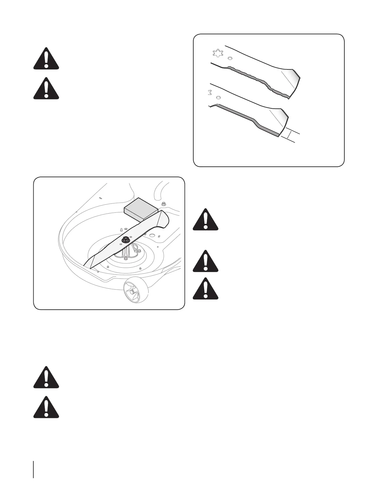
Place a block of wood between the center deck housing 2.
baffle and the cutting blade to act as a stabilizer.
See Fig. 7-5.
Remove the hex flange nut that secures the blade to the 3.
spindle assembly. See Fig. 7-5.
To properly sharpen the cutting blades, remove equal 4.
amounts of metal from both ends of the blades along the
cutting edges, parallel to the trailing edge, at a 25°- to 30°
angle. Always grind each cutting blade edge equally to
maintain proper blade balance. See Fig. 7-6.
CAUTION: If the cutting edge of the blade has
previously been sharpened, or if any metal
separation is present, replace the blades with new
ones.
WARNING! A poorly balanced blade will cause
excessive vibration, may cause damage to the
tractor and/or result in personal injury.
Test the blade’s balance using a blade balancer. Grind 5.
metal from the heavy side until it balances evenly.
NOTE: When replacing the blade, be sure to install the blade with
the side of the blade marked ‘‘Bottom’’ (or with a part number
stamped in it) facing the ground when the mower is in the
operating position.
CAUTION: Use a torque wrench to tighten the
blade spindle hex flange nut to between 70 lbs-ft
and 90 lbs-ft.
Changing the Deck Belt
WARNING! Be sure to shut the engine off, remove
ignition key, disconnect the spark plug wire(s) and
ground against the engine to prevent unintended
starting before removing the belt.
WARNING! All belts on your tractor are subject to wear
and should be replaced if any signs of wear are present.
IMPORTANT: The V-belt found on your tractor is specially
designed to engage and disengage safely. A substitute (non-
OEM) V-belt can be dangerous by not disengaging completely.
For a proper working machine, use factory approved belts.
To change or replace the deck belt on your tractor, proceed as follows:
Remove the deck as instructed earlier in this section.1.
Remove the belt covers by removing the hex washer 2.
screws that fasten them to the deck. See Fig. 7-7.
It may also be necessary to loosen the hex nut on the left 3.
idler pulley to get the belt off the pulley and around the
belt guard.
Carefully remove the deck belt from around the two 4.
spindle pulleys and the two deck idler pulleys. See Fig. 7-7.
To place the new belt, begin by routing the belt around the 5.
two outer spindle pulleys as shown in Fig. 7-7.
Then route the belt around the two deck idler pulleys as 6.
shown in Fig. 7-7.
Figure 7-6
Figure 7-5
 Loading...