21
Operating controls
EN
Operating controls
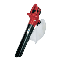
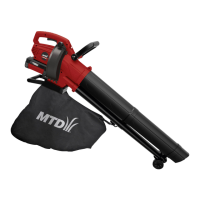
Control elements
R
1 Power pack
2 U-shaped grip
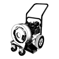
3 Top suction/blow pipe
4 Fastening hook
5 Bottom suction/blow pipe
6 Intake opening
7 Blow opening
8 Transport wheel
9 Turbine wheel cover xing screw
10 Turbine wheel cover
11 Carrying belt
12 Handle
13 On/off switch
14 Rotary switch with motor speed function
15 Quick-release lever for U-shaped grip
16 Release mechanism for leaf bag
17 Vacuum/blow selection lever
18 Vacuum bag with zip
Start-up
Supplementary documentation
Make sure the operating manuals of the
40V FAST CHARGER and the 40V LI-ION
power pack are available. Please read
and understand them before putting the
device into use.
Power pack charging
WARNING!
Risk of injuries or material damage
¾ Only charge the power pack with the 40V
FAST CHARGER.
Attention!
The power pack is supplied partially charged.
Before rst use, fully charge the power pack
using the 40 V FAST CHARGER to ensure the full
capacity of the power pack.
Î Power pack charging must be carried out ac-
cording to the instructions in the supplementary
documentation.
Assembly
WARNING!
Risk of injuries
ÂWhen using the tool, incorrectly tted
parts can lead to severe injuries up to
and including death.
ÂThis tool can only be operated, if all parts
are fully tted and tightened and there
are no damaged parts!
¾ Therefore rst read the entire chapter,
before tting the parts.
¾ Fit the parts carefully and completely.
¾ Use tools as specied.
WARNING!
Risk of injuries
¾ Parts may only be tted and removed
when the motor is switched off and the
power pack removed.
Attaching the handle
ABC
Î Place the U-shaped grip
A
d over the device
housing
B
1
.
Î Push the xing screw through the U-shaped grip
and the housing
B
2
.
Î Apply the xing screw
B
3
.
Î Select your preferred working angle
C
1
.
Î Lock the U-shaped grip by pushing the quick-re-
lease lever in
C
2
.
Attaching the blow/vacuum pipe
ADE
Î Press the top blow/vacuum pipe
A
a a onto
the housing of the device
until it audibly latches
in
D
1
.
Î Fix the top vacuum/blow pipe with the
screw
A
h
D2
.
Î Press the top blow/vacuum pipe
A
b a onto
the housing of the device until it audibly latches
in
E1
.
Î Fix the bottom vacuum/blow pipe with the
screw
A
h
E2
.
 Loading...