EasyManua.ls Logo

MTD Pro HW Series - User Manual

MTD Pro HW Series
20 pages
Print Icon
To Next Page IconTo Next Page
Loading...
Safe Operation Practices • Assembly & Set-Up • Controls & Operation • Product Care
WARNING
READ AND FOLLOW ALL SAFETY RULES AND INSTRUCTIONS IN THIS MANUAL
BEFORE ATTEMPTING TO OPERATE THIS MACHINE.
FAILURE TO COMPLY WITH THESE INSTRUCTIONS MAY RESULT IN PERSONAL INJURY.
OperatOrs Manual
Form No. 769-25875
(October 7, 2020)
Safe Operation Practices ........................................ 2
Assembly & Set-Up .................................................. 7
Controls & Operation .............................................. 8
Product Care ...........................................................12
Replacement Parts ............... Separate Supplement
Attachments & Accessories . Separate Supplement
Parts/Warranty ..................... Separate Supplement
Table of Contents
NOTE: This Operator’s Manual covers several models. Features may vary by model. Not all features in this manual are applicable to all
models and the model depicted may differ from yours.
Pro HW Series
Question and Answer IconNeed help?

Do you have a question about the MTD Pro HW Series and is the answer not in the manual?

Overview

This document is an Operator's Manual for the Pro HW Series mower, providing comprehensive instructions for safe operation, assembly, controls, and maintenance. It emphasizes safety warnings and proper procedures to prevent personal injury and ensure optimal machine performance.

Function Description:

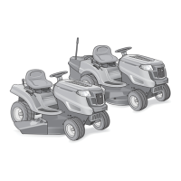
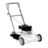
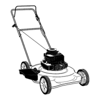
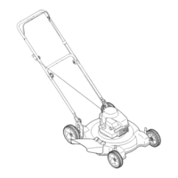
The Pro HW Series mower is a precision piece of power equipment designed primarily for mowing grass. It features a cutting deck with rotating blades, a self-propelled mechanism, and various controls for steering, speed, and blade engagement. The machine is capable of amputating hands and feet and throwing objects if not operated according to safety guidelines. It is not intended for any other purpose than mowing.

Important Technical Specifications:

  • Engine: Internal combustion engine.
  • Fuel: Regular unleaded gasoline (no more than 30 days old). Fuel tank capacity is five gallons.
  • Oil: 20W50 motor oil for the engine and hydrostatic transmission.
  • Tire Pressure: Recommended operating rear tire pressure is 12 psi. Caster wheels are semi-pneumatic and do not require air pressure.
  • Cutting Height: Adjustable via deck lift adjustment pins, with each hole representing a 1/2" change in deck height.
  • Blade Torque: Blade spindle hex flange nut should be tightened to 90-110 ft-lbs.
  • Battery: AGM battery, recommended charge rate 1.1A/14.8V. Contains sulfuric acid and can emit explosive gases.
  • Slope Operation: Not to be operated on slopes greater than 15° (25%).
  • Safety Devices: Operator presence control levers, discharge cover, grass catcher, blade control handle, neutral latch levers, and a spark arrestor (if equipped).
  • Transmission: Dual integrated hydrostatic pumps/transaxles, sealed. Equipped with a transmission oil expansion reservoir.
  • Hour Meter: Records hours of operation and displays service reminders.

Usage Features:

  • Starting the Engine:
    • Electric Start Models: Move speed control lever to neutral (N), disengage PTO, place neutral latch levers in neutral lock position, ensure spark plug wire is connected, pull choke knob up, move throttle lever midway between FAST and SLOW, insert key and turn to START. Release key once engine starts.
    • Recoil Start Models: Put key in ON position, stand on left side away from deck, grasp starter rope handle and pull slowly until resistance, then pull rapidly. Repeat if engine fails to start after three pulls. Operate in FAST throttle setting and disengage choke once started.
  • Stopping the Engine: Place both steering levers in neutral (N) and lock, place speed control lever in neutral (N), disengage PTO (if engaged), move throttle control to SLOW, let engine idle for one minute, turn key counter-clockwise to OFF, and remove key.
  • Engaging the Drive: Start engine, move throttle to FAST. For forward travel, move speed control lever to position 2, hold steering levers and release neutral latch levers, slowly release steering levers. To turn, squeeze the steering lever on the side of the desired turn. To stop forward motion, squeeze both steering levers and place neutral latch levers in neutral lock position. For reverse travel, disengage blades, stop forward motion, check area behind, and slowly squeeze steering levers.
  • Engaging the Blades: Move throttle control lever to FAST, engage operator presence levers, pull up PTO knob until blades rotate.
  • Operating on Slopes: Mow across the face of slopes, never up and down. Exercise extreme caution when changing direction. Avoid holes, ruts, rocks, hidden objects, and wet grass.
  • Deck Height Adjustment: Adjust clevis pin location in deck adjustment pins and collars. Grasp one of the three handles on the deck, lift slightly, remove cotter pin, adjust deck, and reinsert cotter pin.
  • Mowing Pattern: Plan to avoid discharging material toward roads, sidewalks, bystanders, or obstructions. Mow across slopes from bottom to top. Slowly increase speed to match conditions. Change mowing direction by approximately 45° each time to prevent rutting and enhance striped appearance.
  • Transporting: Secure mower with chocks and straps. Push or pull onto trailer/truck bed, never drive. Engage parking brake.
  • Transmission Bypass: Pull out bypass rod and place it down in the slot to manually move the mower short distances.

Maintenance Features:

  • Maintenance Schedule: Includes checks for engine intake screens, cooling fans, exhaust manifold, muffler pipe, muffler shields, top and underside of deck, spindle covers, belt area, fuses, wiring, transmission, axle, fans, fuel level, belts, controls, engine oil level, loose/missing parts. Also includes cleaning/replacing air filter, lubricating pivot arms, changing engine oil/filter, sharpening/balancing blades, lubricating brake lever points, bellcrank pivot, jackshaft couplers, ball joint, checking spark plug, and changing hydraulic oil/filter.
  • Post-Operation Care: Rinse grass clippings from deck underside. Clean around exhaust manifold, fuses, wiring, muffler pipe, muffler shield, engine intake screens, cooling fins, top of deck, spindle covers, belt area, transmission, axle, and fan area.
  • Engine Oil Change: Warm up engine, locate oil drain hose, route to collection container, unscrew hose plug, drain oil, remove oil filter, replace filter, refill with new oil.
  • Battery Maintenance: Keep exterior clean, store with full charge, recharge before returning to service. Disconnect negative cable for extended storage.
  • Deck Leveling: Park on flat surface, measure distance from blade tips to ground on both sides. Adjust bolts on deck lift adjustment pins until front of deck is 1/4-3/8" lower than the rear.
  • Gauge Wheel Adjustment: Set deck to desired height. Check distance between front gauge wheels and ground (should be 1/4-1/2" above ground). Remove lock nut, gauge wheel, hex screw, spacers, and adjust.
  • Replacing Deck Belt: Set parking brake, remove ignition key/spark plug caps, remove PTO belt, remove belt covers, remove belt from pulleys, and route new belt.
  • Replacing Blades: Remove deck, jack up front, secure blade, remove flange lock nut and flat washer, remove blade. Replace in reverse order, tightening to 90-110 ft-lbs. Ensure "Bottom" or "Grass Side" marking faces ground.
  • Sharpening Blades: Clean debris, remove equal amounts of metal from both ends at 25°-30° angle, grind each cutting edge equally, and balance using a blade balancer.
  • Changing Spindle Assembly: Remove deck, jack up front, remove deck cover, drive belts, blade, hex lock screw, flat washer, spindle pulley, flange lock nuts, and support plates. Replace in reverse order, torque hex lock screw to 90-110 ft-lbs and flange lock nuts to 13-20 ft-lbs.
  • Mower Creeping Adjustment: Remove front panel, adjust tracking knob until threaded rod is flush with end, move neutral lock levers to OPEN, loosen jam nut and zero out transmission, move neutral lock levers to CLOSED, loosen jam nut and adjust rod until steering lever is seated in neutral lock lever.
  • Mower Tracking Adjustment: Rotate tracking knob to the left if mower pulls right, or to the right if mower pulls left, in 1/4-turn increments.

MTD Pro HW Series Specifications

General IconGeneral
BrandMTD
ModelPro HW Series
CategoryLawn Mower
LanguageEnglish

Related product manuals