EasyManua.ls Logo

MTD remington - User Manual

MTD remington
22 pages
Print Icon
To Next Page IconTo Next Page
Loading...
Professional Shop Manual
Remington 22” Trimmer Mower
MTD Products Inc. - Product Training and Education Department
NOTE: These materials are for use by trained technicians who are experienced in the service and repair of outdoor power
equipment of the kind described in this publication, and are not intended for use by untrained or inexperienced individuals.
These materials are intended to provide supplemental information to assist the trained technician. Untrained or inexperi-
enced individuals should seek the assistance of an experienced and trained professional. Read, understand, and follow all
instructions and use common sense when working on power equipment. This includes the contents of the product’s Oper-
ators Manual, supplied with the equipment. No liability can be accepted for any inaccuracies or omission in this publication,
although care has been taken to make it as complete and accurate as possible at the time of publication. However, due to
the variety of outdoor power equipment and continuing product changes that occur over time, updates will be made to these
instructions from time to time. Therefore, it may be necessary to obtain the latest materials before servicing or repairing a
product. The company reserves the right to make changes at any time to this publication without prior notice and without
incurring an obligation to make such changes to previously published versions. Instructions, photographs and illustrations
used in this publication are for reference use only and may not depict actual model and component parts.
© Copyright 2013 MTD Products Inc. All Rights Reserved
Question and Answer IconNeed help?

Do you have a question about the MTD remington and is the answer not in the manual?

Summary

Remington 22 Trimmer Mower

Manual Conventions and Safety Indicators

Explains symbols, notes, and safety indicators used within the manual for clarity.

Fasteners

Assembly Instructions

Understanding Model and Serial Numbers

Model Number Breakdown

Details the components and meaning of the product's model number.

Serial Number Breakdown

Details the components and meaning of the product's serial number.

Trimmer Line Replacement

Skid Assembly Maintenance

Spindle Service

Belt Replacement Procedure

Wheels and Axle Service

Debris Screen Maintenance

Overview

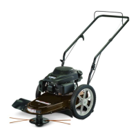
This document is a Professional Shop Manual for the Remington 22" Trimmer Mower, published by MTD Products Inc. in November 2013 (Form Number 769-09540-00). It is intended for trained, professional technicians experienced in servicing and repairing outdoor power equipment. The manual provides supplemental information to assist in repair and overhaul procedures for this specific model.

Function Description:

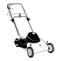
The Remington 22" Trimmer Mower is a wheeled string trimmer designed for clearing heavy growth from unimproved land. It features an engine brake that stops the engine when the engagement control lever is released. The trimmer uses a fixed-length trimmer line, which is easily replaceable. The cutting height can be adjusted by sliding the trimmer line disc up or down the spindle shaft.

Important Technical Specifications:

  • Model Number: 25A-262J710 (example provided in the manual, actual model number on the device may vary, e.g., 25A-26J7783).
  • Serial Number: Example provided as 11243P10039. The serial number indicates engineering level, month and day of production, last digit of the year, plant where it was built, assembly line number, and number of units built.
  • Trimmer Line: Fixed length. Always use 490-040-C035 trimmer line.
  • Fasteners: A combination of metric and fractional inch. Wrench sizes are often identified in the text, and measurements are given in U.S. and metric scales.
  • Skid Assembly: Service part number 982-0143.
  • Spindle: Cannot be serviced; must be replaced as a unit if damaged.
  • Wheels and Axle: Both wheels are supported by inner and outer sealed ball bearings.

Usage Features:

  • Engine Brake Feature: The engine stops running when the engagement control lever is released.
  • Trimmer Line Replacement: The trimmer line is a fixed length and can be easily replaced by folding the new line in half, inserting both ends through the loop near the spindle's edge, pulling them securely beneath the metal tab, crossing the ends, and pulling tightly. The line is automatically trimmed to its final length by a blade under the deflector.
  • Cutting Height Adjustment: The cutting height is adjusted by loosening two wing nuts on the spindle, sliding the trimmer line disc up or down the spindle shaft, and then re-tightening the wing nuts. The skid assembly remains fixed relative to the disc's movement.
  • Debris Screen: A debris screen covers the cooling fan to prevent clogging from trimming debris. It needs occasional cleaning.

Maintenance Features:

  • Skid Assembly Replacement: The skid assembly, which contacts the ground, is a normal wear item and requires replacement. Removal involves turning off the engine, disconnecting the spark plug wire, and removing three nuts and bolts. New hardware is included with the replacement skid assembly.
  • Spindle Replacement: If the spindle is damaged, it must be replaced as a complete unit. The process involves disconnecting the spark plug wire, removing the deflector (which requires removing four nuts and rotating it past the spindle), disconnecting the extension spring, removing the idler pulley assembly, and then removing the bolts securing the spindle to the trimmer base.
  • Belt Replacement: This procedure requires allowing the engine to cool, draining the fuel tank, positioning the trimmer securely, removing the deflector, disconnecting the extension spring, removing the belt keeper bracket, loosening the idler pulley, and then removing the belt from the idler pulley and spindle pulley groove. Further steps involve securing the pulley flywheel, removing the crankshaft bolt, removing the left wheel, sliding the axle, and finally removing the pulley flywheel and belt. Installation is the reverse of removal, followed by a test run.
  • Wheels and Axle Removal: To remove a wheel, unscrew the bolt and washer securing it. If the axle is being removed, the left wheel must be removed first. The axle has a welded stop on the right-hand side that prevents it from sliding or rotating.
  • Debris Screen Cleaning/Replacement: The debris screen should be cleaned occasionally. To remove it, use a screwdriver to push the front locking tab inward, lift it from the engine cover, slip the starter rope through its slot, and then push slightly on the back of the screen to unlock the rear tab. After cleaning, reinstall in reverse order.
  • Fastener Management: If a fastener with a locking feature is worn, it should be replaced or a small amount of releasable thread locking compound (e.g., Loctite® 242 blue) should be applied. Single-use fasteners like cotter pins should not be reused. Other fasteners like lock washers, retaining rings, and hairpin clips can be reused if they show no signs of wear or damage.
  • Lubrication: Lubricant quantity and specification information may be found in the maintenance and assembly sections of the manual, often summarized in tables with special instructions.

Safety Information:

The manual includes important safety warnings:

  • CAUTION: Indicates potentially hazardous situations that may result in minor or moderate injury. Emphasizes preparedness for emergencies (fire extinguisher, first aid, emergency contacts), replacing damaged safety labels, being aware of cumulative hazards, cleaning spills, lifting heavy objects safely, and general awareness of power equipment hazards.
  • WARNING: Indicates potentially hazardous situations that could result in death or serious injury. Advises on grooming and attire (no loose clothing, secured long hair, no jewelry) and protective gear (eye protection, gloves, armored footwear, hearing protection, chemically resistant gloves, respirator, tinted eye protection for cutting/welding, flame-resistant headgear/jacket/chaps for cutting/welding).
  • DANGER: Indicates imminently hazardous situations that will result in death or serious injury. Specifically warns about carbon monoxide (CO) from running engines, emphasizing the need for well-ventilated areas or exhaust evacuation systems with make-up air when running engines indoors.

The manual also notes that instructions, photographs, and illustrations are for reference only and may not depict actual model and component parts. It stresses that common sense in operation and safety is assumed, and MTD is not liable for poor text interpretation or execution of procedures. Users uncomfortable with any procedures should seek professional help.

MTD remington Specifications

General IconGeneral
BrandMTD
Modelremington
CategoryLawn Mower
LanguageEnglish

Related product manuals