6.31 MTL5113P fail-safe switch/proximity
detector interface
With the MTL5113P, a fail-safe switch/proximity detector located in the
hazardous area can control an isolated, fail-safe electronic output. The
MTL5113P unit also provides line-fault detection alarm contacts.
The MTL5113P is for use with P + F TÜV-approved fail-safe sensors.
Correct operation of fail-safe output and LFD, where applicable, is
indicated by amber and red LEDs on top of the unit. Amber is ON
when fail-safe output is energised. Red is ON if a line fault is detected.
Fail-safe output is OFF if the incorrect sensor current, an open circuit
or a short circuit is present in the sensor circuit.
MTL5113P input/output characteristics are shown in table 6.14.
Table 6.14
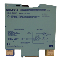
6.31.1 Wiring connections
See figure 6.71 For wiring connections.
Note: Switch-type sensors must always be fitted with resistors, as shown.
*
Series resistor should be in the range 1k3
Ω
- 1k5
Ω
6.31.2 Line fault detection
(See section 3.1.4 for definition of a line fault
)
If an input line fault (open- or short-circuit) is detected, a red LED on top
of the unit goes ON, the LFD contacts open and the LFD output is de-
energised providing an alarm output. The fail-safe output is also de-
energised and the amber output status LED on top of the unit goes OFF.
29
INM5000-6 Jul 2010
6.31.3 Testing
Make the safe- and hazardous-side connections shown in figure 6.72.
With an ohmmeter, check that the status of the outputs is as follows:
6.32 MTL5314 trip amplifier for 2– or 3– 2
wire transmitters
The MTL5314 connects to a 2– or 3– wire 4 to 2mA transmitter or
current source located in the hazardous area. It supplies one or two
configurable alarm signals to the safe area via changeover relays.
Each relay may be configured individually to signal an alarm condition
when the input signal is greater than or less than a pre-set value.
In addition, the MTL5314 can be connected in series to the hazardous-
area side of an MTL5042 4 to 20mA repeater power supply (or equivalent
device) to provide two trip alarm outputs direct from the transmitter signal
(see schematic diagram). Looping the transmitter signal through the MTL
5314 (via terminals 1 and 3) does not affect HART® communications.
Terminals 1 and 3 meet clause 5.4 of EN50020: 1994 and have the
following parameters: U ≤ 1.5V, I ≤ 0.1A, P ≤ 25mW. They can be
connected without further certification into an IS loop with open circuit
voltage of not more than 28V. See certificate for further details.
6.32.1 Wiring connections
See figure 6.73 for wiring connections.
If terminals 1 and 3 provide a 4 to 20mA loop to a HART transmitter,
HART communication can be superimposed on the 4 to 20mA signal.
Note: Reactive loads must be adequately suppressed
.
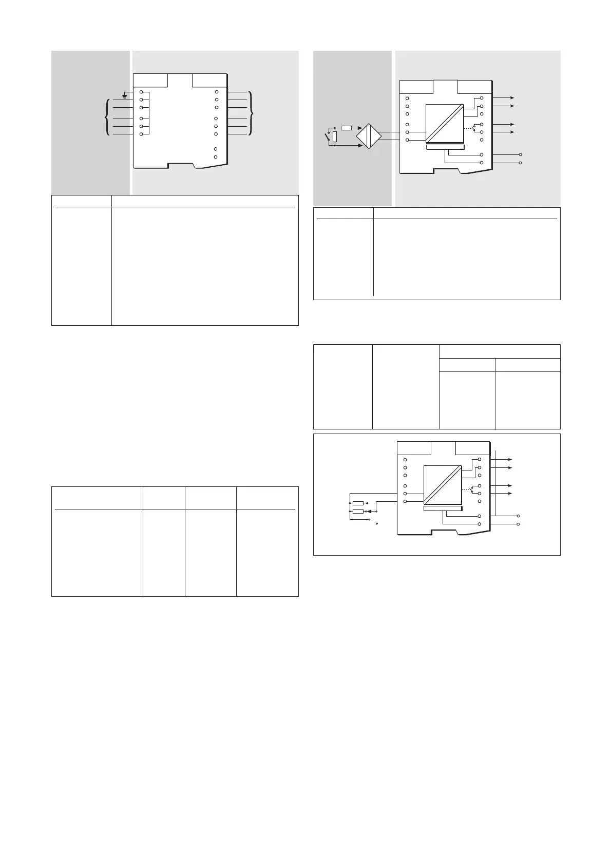
Figure 6.70: MTL5099 wiring diagram and connections
Hazardous area Safe area
Input value in Fail-safe Operation LFD contacts
sensor circuit output
2.9mA < Is < 3.9mA ON Normal Closed
Is<1.9mA and Is>5.1mA OFF Normal Closed
Is<50µA OFF Broken line Open
Is>66mA OFF Shorted line Open
Terminal Function
1 Input –ve
2 Input +ve
3 Output –ve
7 Output +ve
10 LFD
11 LFD
13 Supply –ve
14 Supply +ve
Figure 6.71: MTL5113P wiring diagram and connections
Hazardous area Safe area
Input Fail-safe Line fault
output contacts output
open-circuit de-energised open de-energised
short-circuit de-energised open de-energised
1k4Ω energised closed energised
10kΩ de-energised closed energised
Artisan Technology Group - Quality Instrumentation ... Guaranteed | (888) 88-SOURCE | www.artisantg.com