L
Laura KennedyAug 16, 2025
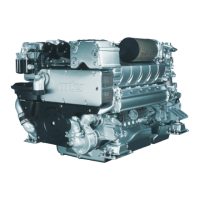
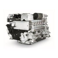
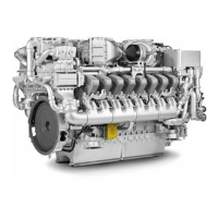
What to do if my MTU 12 V 2000 M51B does not turn when starter is actuated?
- LLaura CookAug 16, 2025
If your MTU Engine doesn't turn when the starter is activated, several issues could be the cause. The battery may be discharged or faulty, in which case you should charge or replace it. Check if cable connections are properly secured. Starting-air pressure might not be available, so check the connections and the main valve of the compressed-air system. Other potential causes include a blocked running gear, a missing or defective limit switch, or faulty wiring. For engine wiring or starter issues or problems with starting-air pressure, it is best to contact service.