EasyManua.ls Logo

MTU 12 V 2000 P12 - User Manual

MTU 12 V 2000 P12
187 pages
Print Icon
To Next Page IconTo Next Page
Loading...
Operating Instructions
Diesel engine
12 V 2000 P12
16 V 2000 P12
MS150025/02E

Table of Contents

Questions and Answers

  • C
    Christopher SmithAug 15, 2025
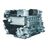
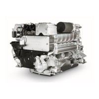
    Why MTU 12 V 2000 P12 does not turn when starter is actuated?
    • W
      watkinsandrewAug 15, 2025
      If the MTU Engine doesn't turn when the starter is activated, possible causes include a flat or defective battery (charge or replace it), faulty cable connections (check if they are properly secured), engine wiring or starter issues (check cable connections), unavailable starting-air pressure (check connections and pressure), or loose plug-in connections (check connections).
  • J
    Jennifer FriedmanAug 18, 2025
    Why MTU 12 V 2000 P12 turns but does not fire?
    • K
      Kristine WalkerAug 18, 2025
      If the MTU Engine turns but doesn't fire, it could be due to poor rotation by the starter because of a flat or defective battery (charge or replace the battery) or air in the fuel system.
  • J
    John SerranoAug 21, 2025
    What causes black exhaust gas from MTU 12 V 2000 P12?
    • J
      justin88Aug 21, 2025
      Black exhaust gas from the MTU Engine can be caused by a clogged air filter (check the contamination indicator), a faulty injector, a defective injection pump, or the engine being overloaded.
  • D
    djenkinsAug 25, 2025
    Why MTU 12 V 2000 P12 speed not steady?
    • G
      gentrymarciaAug 26, 2025
      An unsteady MTU Engine speed can be attributed to a faulty injector, a defective injection pump, or air in the fuel system.
  • A
    Ashley LeblancAug 28, 2025
    What causes white exhaust gas from MTU Engine?
    • H
      Heather HardyAug 28, 2025
      White exhaust gas from the MTU Engine may be caused by the engine not being at operating temperature (run engine to reach operating temperature) or water in the fuel (check fuel system at fuel prefilter).
  • W
    williamsbrentSep 1, 2025
    What causes blue exhaust gas from MTU 12 V 2000 P12 Engine?
    • H
      Holly WilliamsSep 1, 2025
      Blue exhaust gas from the MTU Engine can be caused by the engine oil level being too high (drain engine oil) or the oil separator/pre-separator of the crankcase breather being clogged (replace it).
  • Y
    Yolanda ThomasSep 4, 2025
    What causes MTU 12 V 2000 P12 to fire unevenly?
    • B
      Barbara ParkerSep 4, 2025
      An MTU Engine firing unevenly may be due to a faulty injector, a defective injection pump, or air in the fuel system.
  • T
    Thomas WalkerSep 7, 2025
    What causes charge-air temperature too high in MTU Engine?
    • P
      Pamela FerrellSep 7, 2025
      If the charge-air temperature is too high in the MTU Engine, it could be due to incorrect engine coolant treatment or contamination. Check the fan and air inlet/outlet ducts.
  • R
    Randy RiggsSep 12, 2025
    What causes charge-air pressure too low in MTU Engine?
    • J
      jessica93Sep 12, 2025
      Low charge-air pressure in the MTU Engine can be caused by a clogged air filter (check the contamination indicator).

Summary

Safety

Important provisions for all MTU engines or systems

General information about safe operation, correct use, and modifications.

Personnel and organizational requirements

Operator responsibilities, training, and protective equipment.

Transport

Instructions for lifting, securing, and setting down the engine during transport.

Safety regulations for maintenance and repair work

Safety procedures before, during, and after maintenance and repair work.

Fire prevention and environmental protection, auxiliary materials, fluids and lubricants

Guidelines for fire safety, noise, disposal, and handling of fluids/lubricants.

Standards for safety messages in the text

Explanation of safety message signal words (DANGER, WARNING, CAUTION, NOTICE).

ATEX precautions (if applicable)

Additional safety precautions for potentially explosive atmospheres.

General Information

Engine side and cylinder designations

How engine sides and cylinders are designated and numbered.

Engine layout

Diagram and list of major engine components.

Use

Functions, features, and design of the MDEC system and its components.

ECS-5 - Use of devices

Central control and monitoring device for the engine governor and its software structure.

MDEC - Functions

Overview of engine control functions like start, stop, override, and monitoring.

Peripheral Interface Modules (PIMs)

Design and function of PIMs for processor boards MPU 23 and MPU 27.

Printed circuit board SCB 3

Purpose, design, features, and use of the SCB 3 interface extension.

Technical Data

12;16 V 2000 P12 engine data

General and power-related data for 12/16 V 2000 P12 engine models.

Firing order

Specifies the sequence of cylinder firing for 12 V and 16 V engines.

Engine - Main dimensions

Physical dimensions (length, width, height) for 12 V and 16 V engine models.

SAM

Technical data, use, application, and EMI/EMC compliance of the SAM module.

SCB 3 - Technical data

Technical specifications for the SCB 3 printed circuit board.

Operation

LOP - Controls

Description of function keys and their meanings on the Local Operating Panel (LOP).

Putting the engine into operation after extended out-of-service-periods (>3 months)

Preconditions and steps for re-commissioning the engine after long periods of inactivity.

Putting the engine into operation after scheduled out-of-service-period

Preconditions and steps for re-commissioning the engine after routine maintenance.

Start engine in manual mode (testing mode)

Steps for starting the engine in manual mode for testing purposes.

Safety system - Override

How to bypass safety functions and initiate an emergency start.

Operational checks

Routine checks to perform on the engine during operation.

Stop engine in manual mode (testing mode)

Procedures for stopping the engine in manual mode.

Emergency stop

How to perform an emergency stop from the Local Operating Panel (LOP).

After stopping the engine - Engine remains ready for operation

Actions to take after stopping the engine to keep it ready for immediate restart.

After stopping the engine - putting the engine out of service

Steps for preparing the engine for extended storage or de-commissioning.

Plant cleaning

Procedures and safety precautions for cleaning the engine plant.

Maintenance

Maintenance task reference table [QL1]

A reference table linking maintenance tasks to their respective page numbers.

Troubleshooting

Troubleshooting

Common engine problems and their potential causes and solutions.

Fault indication on printed circuit board SAM

Interpreting fault codes and messages displayed on the SAM.

ECU alarms

Understanding and responding to alarms generated by the Engine Control Unit (ECU).

Task Description

Engine

Procedures related to the engine, including barring and testing.

Cylinder Liner

Inspection and interpretation of cylinder liner condition.

Crankcase Breather

Maintenance tasks for the crankcase breather system.

Valve Drive

Procedures for checking and adjusting valve clearance.

Injection Pump; HP Pump

Replacement, removal, and installation of the injection pump.

Injection Valve; Injector

Replacement, removal, and installation of the injector.

Fuel System

Maintenance tasks for the fuel system, including valves and venting.

Fuel Filter

Procedures for replacing, cleaning, draining, and flushing fuel filters.

Charge-Air Cooling General, Left-Hand Side

Checking intercooler condensate drains for blockages and leaks.

Air Filter

Procedure for replacing the air filter.

Air Intake

Checking the position of the service indicator signal ring on the air filter.

Starting Equipment

Checking the starter's condition, securing screws, and wiring.

Lube Oil System, Lube Oil Circuit

How to check and change the engine oil level and filter.

Oil Filtration; Cooling

Steps for replacing the engine oil filter.

Coolant Circuit, General, High-Temperature Circuit

Identifying drain and vent points for the engine coolant circuit.

Engine coolant - Level check

Methods for checking engine coolant level at filler neck and via sensor.

Engine coolant - Change

Steps for changing the engine coolant.

Engine coolant - Draining

Procedure for draining the engine coolant.

Engine coolant - Filling

Steps for filling the engine coolant system.

Coolant pump - Relief bore check

Checking the relief bore of the coolant pump for discharge and dirt.

Low-Temperature Circuit

Procedures for filling, draining, and checking charge-air coolant.

Belt Drive

Inspecting drive belts for wear and damage.

Engine Mounting; Support

Checking engine mounts for cracks, deformation, and setting dimensions.

Wiring (General) for Engine;Gearbox;Unit

Inspecting engine wiring for secure connections and damage.

Accessories for (Electronic) Engine Governor; Control System

Cleaning engine governor, monitoring unit, and their connectors.

Emergency Instrumentation (Local Operating Panel)

Visual inspection and test procedures for the Local Operating Panel (LOP).

Engine Governor Assignment and Circuitry

Engine Governor

Details on engine governor channel circuitry and MDEC assignment.

Connector Assignment

Pin assignments for various connectors (X1, X2, X3, X4, X5, X6).

Appendix A

Abbreviations

Glossary of abbreviations used in the manual.

MTU contact persons;service partners

Information on how to contact MTU for support and spare parts.

Appendix B

Special Tools

List of special tools required for maintenance and their part numbers.

MTU 12 V 2000 P12 Specifications

General IconGeneral
Engine TypeDiesel
ConfigurationV12
Torque6000 Nm
Fuel SystemCommon Rail
Cooling SystemLiquid-cooled

Related product manuals