MUELLER
®
B-101
TM
and B-100
TM
Drilling and Tapping Machines
Operating Instructions
10 11
4. Pull the bypass valve to “relieve”
position which will release the
pressure from the machine and
indicate the tightness of the
connection between the stop or plug
and the pipe. If there is full pressure
flow from the bypass valve, the
screw plug has not released and the
stop or plug should be screwed in
again a little tighter than before and
another attempt be made to release
the screw plug.
Remove The Machine
1. Loosen the chain hook nuts.
2. Unhook the chain and remove
hooks and chain.
3. Remove the machine, saddle and
gaskets. (Q.)
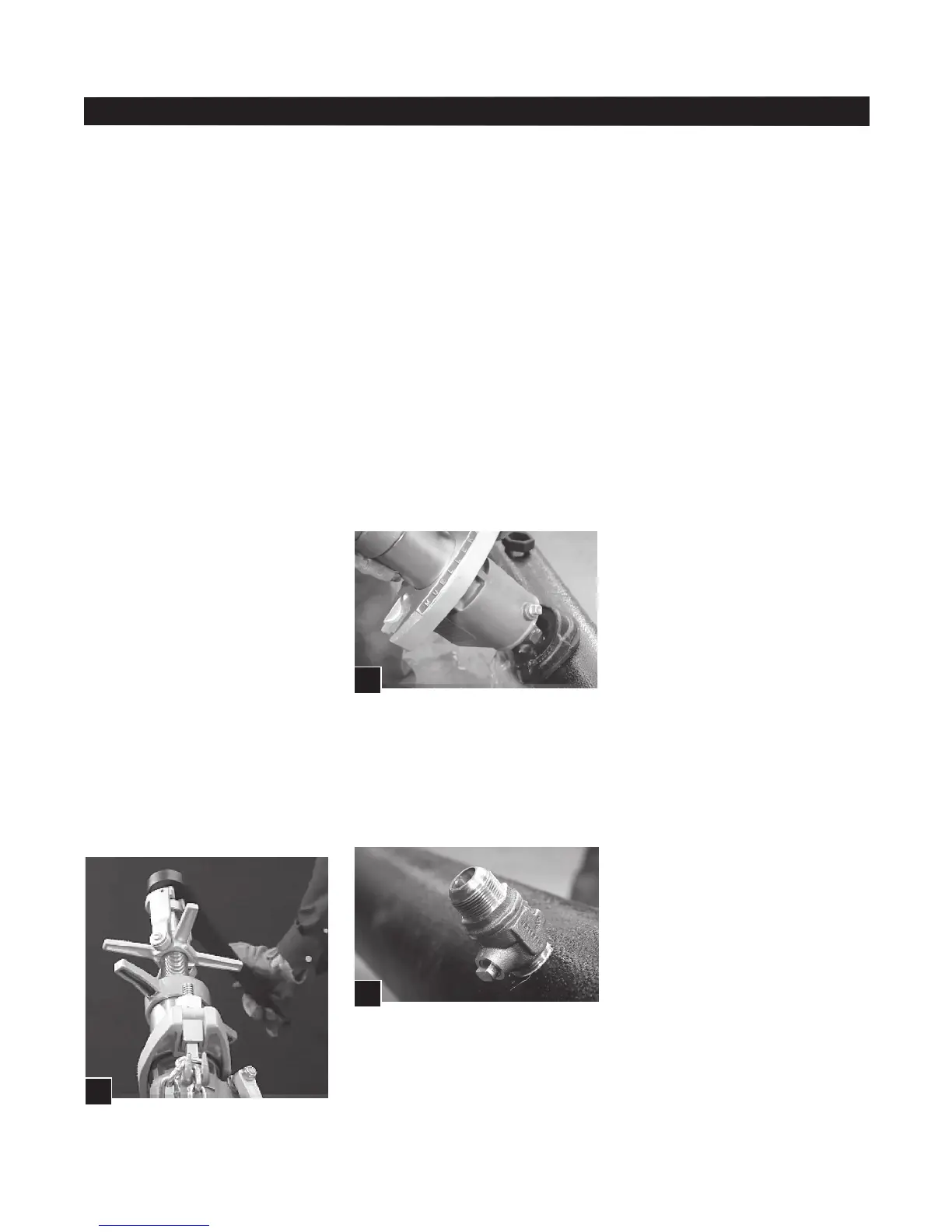
4. Tighten the stop or plug into the
pipe permanently with a flat jaw
wrench on the valve body.
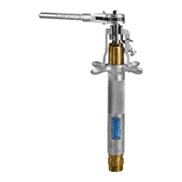
5. If using an E-Z Release screw
plug, remove the nut part from the
stop with the E-Z Release screw plug
wrench furnished with machine. (R.)
Extracting Stop or Plug Installed
in Pipe Under Pressure
1. Shut off the stop.
2. Disconnect service line piping.
3. Slightly loosen the stop or plug
using a wrench on the inlet side.
5. Adjust the feed yoke over thrust
collar on boring bar.
6. Rotate boring bar clockwise
while feed yoke is also carefully
rotated clockwise. After the threads
on the stop or plug have engaged
the tapped hole in the main, rotation
of the feed yoke may be stopped
and the yoke removed from contact
with the thrust collar, while the fitting
is screwed into its seat. When the
stop or plug is being inserted in thin
wall or asbestos-cement pipe or into
pipe under high pressure, the feed
yoke should be used to follow the
collar all the way down.
7. Screw the stop or plug into the
tapped hole until it feels solid.
IMPORTANT: DO NOT attempt to
force it to its permanent tightness
by means of the machine.
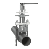
Release The Screw Plug
1. Adjust lever on ratchet handle for
clockwise rotation.
2. Turn the ratchet handle counter-
clockwise to take out the play
and strike the end of the handle
a sharp blow counter-clockwise
with the palm of the other hand.
(P.) This will release the threaded
connection between the screw plug
and the stop or plug. If using on E-Z
Release screw plug, this will release
the threaded connection between
the two parts of the screw plug.
3. Rotate ratchet handle counter-
clockwise until screw plug is
completely free.
4. Separate the two parts of the
extracting tool.
5. When using an extracting tool
having inside threads, screw the nut
into the outside threads of the stop
very securely using the right hand
thread. When using an extracting
tool having outside threads, screw
the plug into the inside threads of
stop or plug very securely using the
right hand threads.
6. Unscrew the feed cap containing
the boring bar assembly from the
cylinder of the machine (2
1
/2 turns).
7. Open flop valve to its wide open
position by pushing lever handle
down. If desired, handle screw may
be engaged into socket on side of
body to retain flop valve in open
position during this operation.
8. Assemble large saddle gasket,
saddle, small saddle gasket and the
body and cylinder of the machine
centrally over the installed valve or
plug.
9. Place chain hooks and washers
into chain yoke and attach chain.
10. Hand tighten chain hook nuts.
See instructions “Attach The
Machine to The Pipe” section on
page 5.
11. Attach the shank part of the
extracting tool into the boring bar
socket being sure the knockout pin
is in its outward position and the
drive pins align with slots in the
boring bar.
12. Tighten tool retaining screw in
boring bar using small socket end
of chain hook nut and tool retaining
screw wrench.
13. Push the feed sleeve and cap
down on the boring bar as far as
possible.
14. Attach boring bar, feed sleeve
and tool assembly to cylinder of
machine and tighten cap securely
(2
1
/2 turns). Be sure boring bar is
held in its upper position while cap
is being attached.
P.
Q.
R.
 Loading...