MUELLER
®
B-101
TM
and B-100
TM
Drilling and Tapping Machines
Operating Instructions
9
Attach Stop Or Plug To Boring
Bar
IMPORTANT – Check to be sure
the stop to be installed is fully
closed.
1. Screw together the proper screw
plug and the stop or plug to be
inserted. Be sure these threads
screw together freely without
binding.
When using an E-Z Release screw
plug, also lubricate and check the
acme threads between the two parts
of the screw plug. (N.)
2. Slide knockout pin in boring bar
socket to its outward position using
pin extending through bottom of
boring bar bearing as a handle.
3. Insert shank end of screw plug
into boring bar socket aligning
driving pins on tool with slots in end
of boring bar and firmly push screw
plug and stop assembly to its rear
most position. (O.)
4. Tighten tool-retaining screw in
boring bar using small socket end
of chain hook nut and tool retaining
screw wrench.
5. Push the cap down on the boring
bar as far as possible.
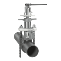
6. Coat the inlet threads of the
corporation stop or with non-
hardening pipe thread sealant or
Teflon
®
tape (P.)
4. With the boring bar in its
uppermost position, close flop valve
by loosening handle screw (if lever
handle was locked open) and raising
upward on lever handle.
If machine is being operated on low
pressure, it is advisable to retain
flop valve in closed position by use
of handle screw on lever handle.
The handle screw in lever handle is
tightened against wedge on side of
body.
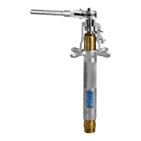
5. With flop valve closed, pull
bypass valve to “relieve” position.
This relieves the pressure above
the flop valve and allows the line
pressure to keep the flop valve
closed, which is assisted by handle
screw if it is used. (L.)
6. Retain boring bar in its uppermost
position, while feed sleeve and cap
and boring bar assembly is removed
from cylinder of machine.
7. Remove combined drill and tap
from boring bar by first loosening
the tool retaining screw with the
socket end of the chain hook nut
and tool retaining screw wrench, but
DO NOT remove screw.
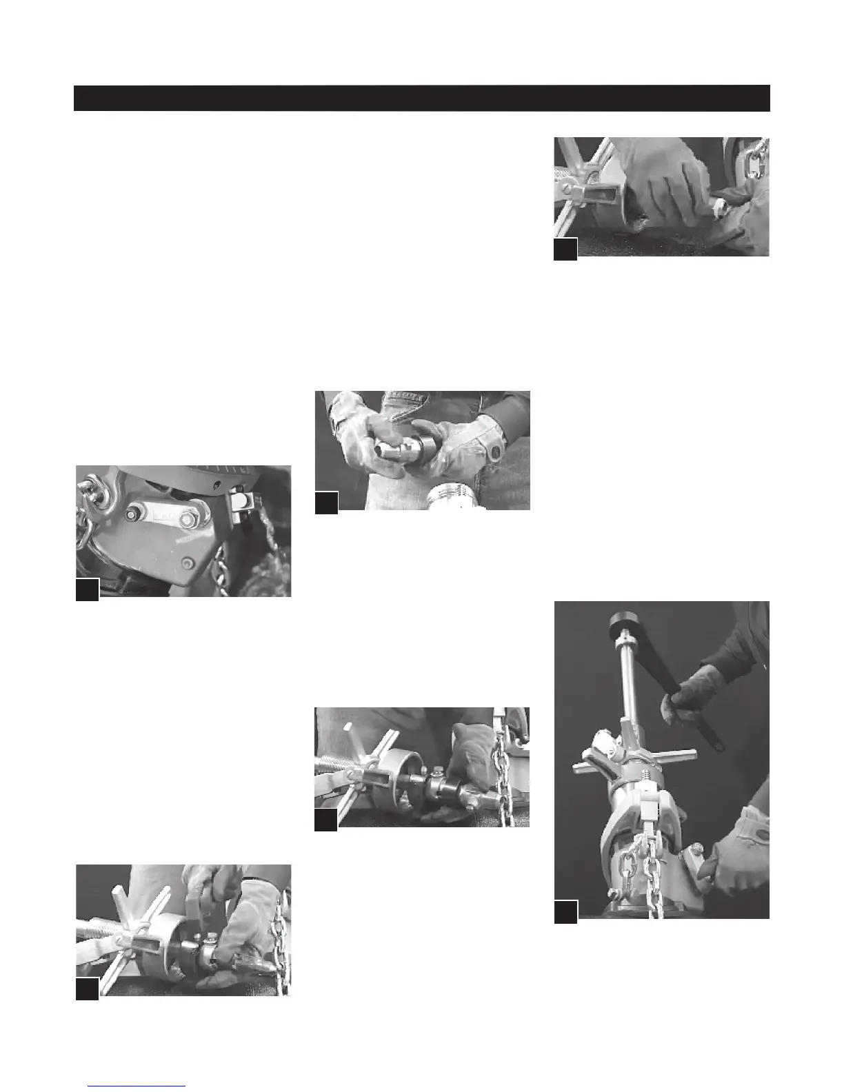
8. Strike the head of the knockout
pin with a light blow to loosen the
combined drill (or shell cutter) and
tap. (M.)
9. Remove the combined drill and
tap from boring bar socket.
7. Replace feed sleeve and cap
and boring bar assembly onto the
cylinder of machine and tighten cap
securely so that a pressure tight
joint is formed.
Insert The Stop Or Plug
1. Hold boring bar assembly in
uppermost position. Push bypass
valve to “bypass” position.
2. Attach ratchet handle and set for
clockwise rotation.
3. Open flop valve by loosening
handle screw, If it was tightened,
and pushing lever handle all the
way down. Handle screw should be
engaged into socket on side of body
to retain flop valve in open position
during this operation. (Q.)
4. Push the boring bar down until
the inlet threads of the stop or plug
contact the threads in the pipe. For
pressure greater than 90psi use a
power clevis to force the boring bar
down. See Instructions “F-3”.
L.
M.
N.
O.
P.
O.
 Loading...