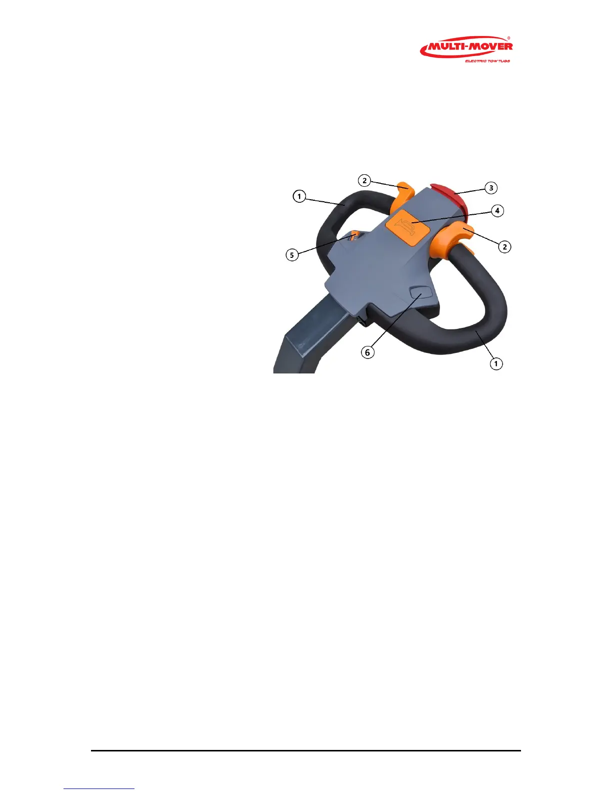
Fig. 2 Tillerhead
1 Handle, black
2 Drive switch, throttle forwards / backwards
3 Safety switch, belly button
4 Signal switch, Horn (# =Optional)
5 Potentiometer, stepless speed control
6 Hydraulic or electric hitch (# =Optional)
Steering handles (2.1)
The steering handle (1) with bar is a fixed part of the Multi-Mover XL75, moving to the left means
driving to the left, and vice versa.
Safety switch (2.2)
When pressing the safety switch (risk of getting jammed), the Multi-Mover XL75 will stop immedi-
ately.
In order to start again, the drive switch must first be placed in the neutral position.
# Coupling point upward (2.6), # coupling point downward (2.6)
Optionally, the coupling point can be moved upward/downward with an actuator (spindle motor).
This serves, for instance, to make it easier to move a tandem aXL75e trailer.
# Signal switch (2.4) only upon request
Optionally, a horn can be connected to the signal switch (5).
Drive switches (2.2), left and right from the centre