10 Modifications reserved Document: IV_MCEE_2016_11_22
4.5.2 Fitting the return air ducts
Noise problems are often created if air heaters are used with
very short and/or undersized return air ducts. These problems
can be avoided by:
• insulating the return air ducts by means of an acoustic
liner;
• installing a sound damper in the return air ducts;
• making sure the that there are at least 2 generously sized
90° turns in the ducting system;
• Increasing both diameter and length of the return air
ducts.
You can connect the return air duct to the left, right or the
bottom of the unit. We strongly suggest using only the bottom
return air opening (please remove the cut-out when commis-
sioning). If possible, install the unit on an insulated plenum, on
which side return ducts can be connected. If you do not have
sucient free space to use an insulated return air plenum, it
is possible to install an optional side filter frame. However, in
doing so, a large part of the acoustic insulation is lost. Always
use a return air duct and return air from OUTSIDE of the com-
bustion compartment. If you do wish to apply an open return,
make sure that there are (will be) no other devices with open
combustion circuit in the installation area.
4.6 Commissioning
4.6.1 Switching the apparatus ON an OFF
Normally the machine shall permanently be supplied with
mains power. At the installation or maintenance stage you
may proceed as follows to switch on or o the device.
Proceed as follows to switch the machine ON:
• Connect the mains power.
• Set the room thermostat at the desired setting.
Proceed as follows to switch the machine OFF:
• Set the room thermostat 5°C lower than the actual tem-
perature.
• Disconnect mains power.
4.6.2 Setting the air temperature
You will need to set the minimum and maximum air tempe-
rature of the unit. This can be done by the display. For more
information please refer to chapter 3.
4.6.3 Setting the air flow
You will need to set the minimum and maximum air flow of
the unit. This can be done by the electronic display. For more
information please refer to chapter 3.
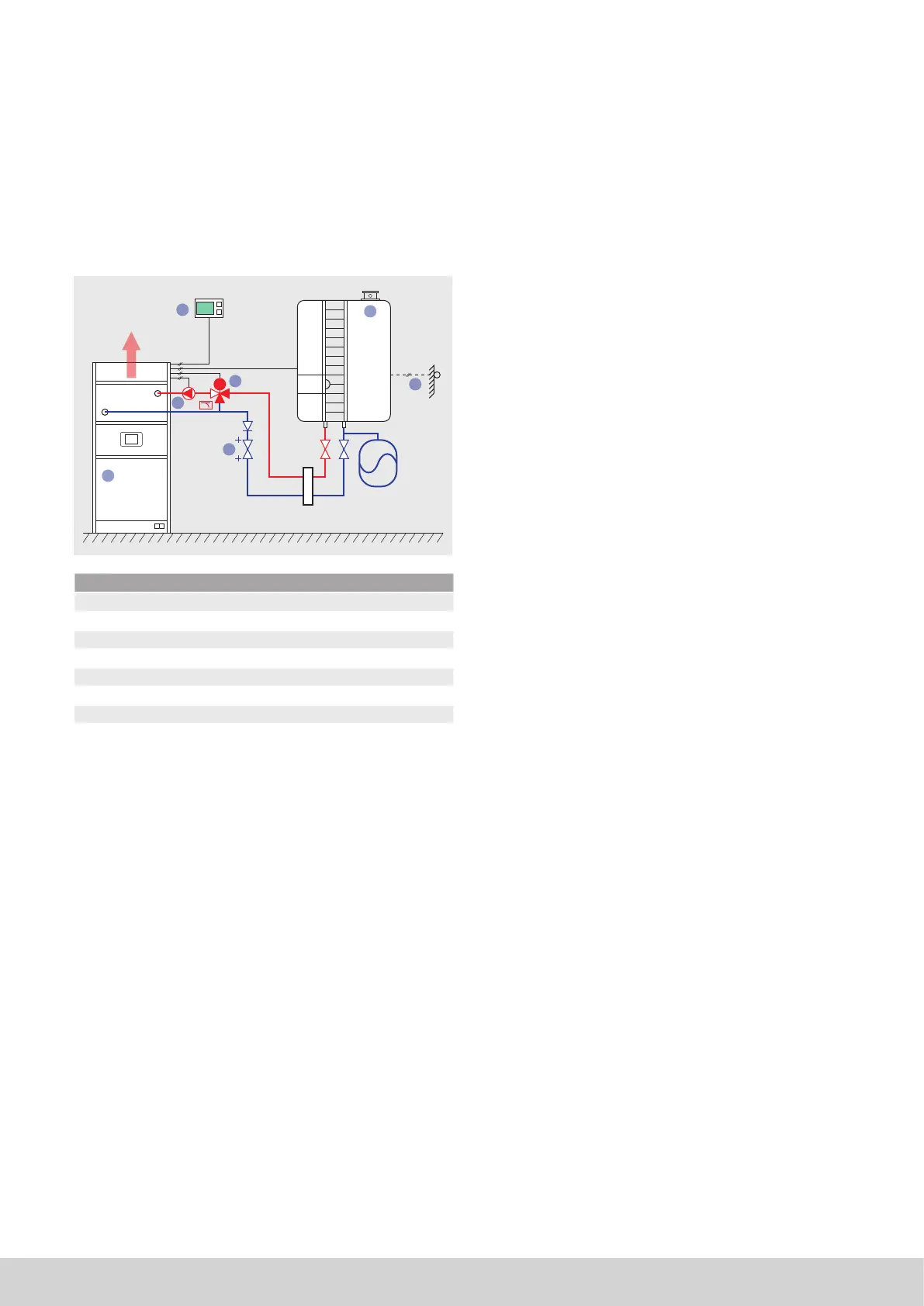
4.4.2 Hydraulic installation, extended version
• We suggest using valves with following KVS factors:
MC20: KVS10
MC30: KVS10
MC40: KVS16
• We suggest that you do not give priority to the hot water
system but install the system in such a way that both
heating and hot water demand can run together.
• Best results are obtained if the boiler temperature is con-
trolled via a weather compensator.
1
2
3
4
22
2
5
M
6
7
Number Function
1 Heat exchanger MC-EE
2 Boiler
3 Thermostat connected to MC-EE
4 Optional outside sensor
5 One-way valve
6 Circulator (Field wiring)
7 3-way valve; 0-10V control voltage (O1)
Attention
I The 3-way valve must be powered externaly
4.5 Installing the ducting system
4.5.1 Fitting the supply ducts
Fit a matching supply air on the unit. The height of the plenum
should be at least as high as the width of the unit. The supply
air plenum should, like the supply ducting system, be thermally
insulated. The supply air duct should be of a sucient size
to permit air displacement with normal speeds and pressure
losses.