Page <4> V1.012/10/22
Newark.com/multicomp-pro
Farnell.com/multicomp-pro
sg.element14.com/b/multicomp-pro
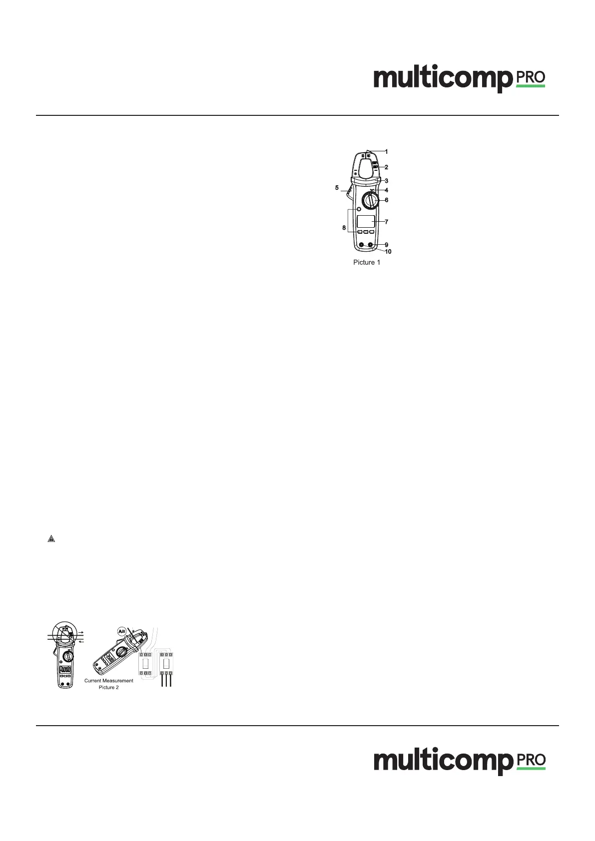
7. External Structure
1) NCV sensing end
2) Clamp jaws
3) Hand guard
4) LED lndicalor
5) Jaw opening trigger
6) Function scale knob
7) LCD display
8) Function buttons
9) Signal input jack (red and positive+)
10) COM input jack (black and negative -)
8. Button Description
SELECT Button
In composite scale, press this butlon lo switch between the corresponding functions or ranges;
HOLD/BACKLIGHT Button
Short press this button lo enter/exit the data hold mode, and long press (about 2s) this button lo tum on/o the backlight.
MAXIMIN Button
(valid for ACV/DCV, ACAIDCA, °C/°F, resistance and capacitance scales)
Short press this button to enter the maximum/minimum measurement mode and long press this button to exit.
REL Button
(valid for ACV/DCV, DCA, °C/°F, and capacitance scales).
Press this button to store the current reading as a reference for future readings. When the LCD display value is reset to zero,
the stored reading will be subtracted from the future readings. Press this button again lo exit the relative value mode.
9. Operating Instructions
9.1 AC/DC Current Measurement (Picture 2)
• Select the corresponding current range.
• Press the trigger lo open the clamp jaws, and fully enclose one conductor.
• Only one conductor can be measured at a time, or the measurement reading will be wrong.
Caution:
• Do not insert the testing leads during current measurement to avoid electric shock.
The current measurement must be taken with safeguard protection.
Press the REL button to return to zero before the DC current measurement, and meanwhile the centre hole of jaw should be
perpendicular to the current direction lo ensure accuracy.
The open circuit zeroing reading may be relatively large after (high) DC current measurement. Please perform theAC current
detection again to counteract the remanence signal by alternating electric eld.
9.2 AC/DC Voltage and Voltage Frequency (% duty cycle)
Measurement (Picture 3)