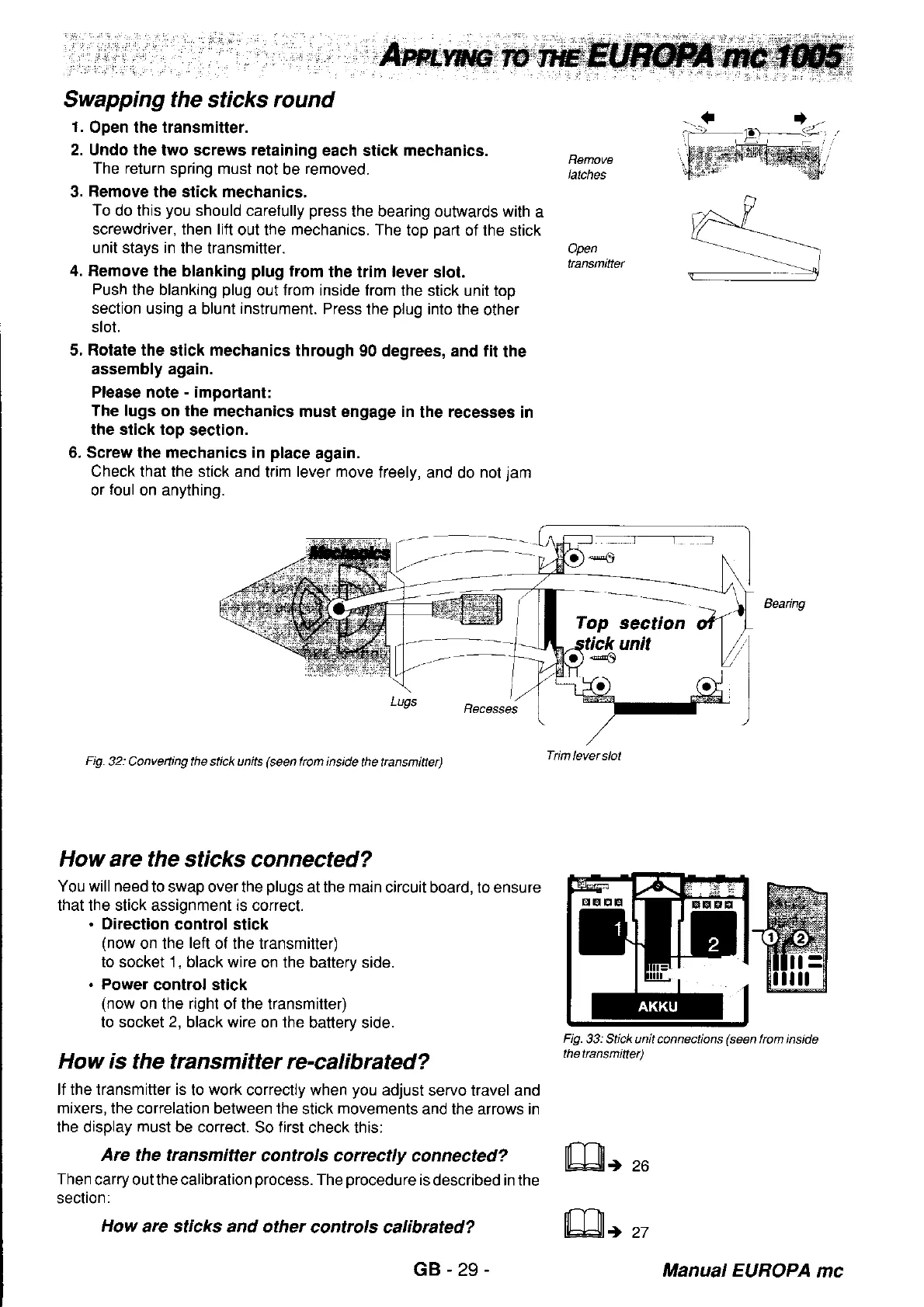
Swapping the
sticks
round
1.
Open the transmitter.
2. Undo the
two screws
retaining
each stick
mechanics.
The return
spring must not
be
removed.
3. Remove the stick mechanics.
To
do this
you
should carefully
press
the bearing outwards with
a
screwdriver, then lift
out the mechanics. The
top
part
of the stick
unit stays in
the transmitter.
4. Femove
lhe blanking
plug
from
the
trim
lever
slot.
Push
the blanking
plug
out from inside from
the stick unit top
section
using a blunt
instrument.
Press
the
plug
into the
other
slot.
5. Rotate the
stick
mechanics
through
g0
degrees, and tit
the
assembly again.
Please note
-
importanl:
The lugs
on the mechanics
must engage in
the recesses in
the stick top
section.
6. Screw the mechanics in
place
again.
Check that the stick and
trim
lever move
freely,
and do
not
jam
or
toul
on anything.
Lugs
Fig.32:
Conveiing the stick units
(seen
from inside
the ttansmitte]
How are the
sticks connected?
You will need
to swap over the
plugs
at the main
circuit board, to ensure
that the stick assignment is correct.
.
Direction control stick
(now
on the
left
of the transmitter)
to socket 1
,
black wire
on the batterv side.
.
Power
control stick
(now
on the
right
of the lransmitter)
to socket
2,
black wire on the
battery side.
How is
the transmitter re-calibrated?
lf the transmitter is
to
work
correctly when
you
adjust
servo travel and
mixers,
the correlation between the
stick
movements
and the arrows in
the display
must
be correct.
So
first
check this:
Are the transmitter
controls correctly
connected?
Then
carry out the calibration
process.
The
procedure
is
described in the
section:
How
are sticks and other
contrcls calibrated?
Remove
latches
Open
tan6mitter
Beanng
Fig.33:
Stick unit connections
(seen
frcm inside
thettansmittet)
Tim
lever slot
GB-29
il-nr
lbJ3)|r
27
Manual EUROPA
mc
 Loading...


