9
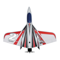
Wingspan: 920 mm
Overall length: 885 mm
All-up weight: approx. 980 g
Wing area: 19 dm²
Wing loading: 51.5 g/dm²
RC functions: Aileron, elevator, throttle, rudder
Specication
Assembly instructions
Before assembly
Use the list of components on page 4 and
Fig. 01
to check the
completeness of the components supplied.
We recommend using a soft, clean and at surface to ensure the model is not
damaged during assembly. Always use, unless otherwise specically stated,
Zacki
®
Elapor CA instant adhesive to glue the model.
1. Assembling the wings
Feed the servo cable of the wing
6
through the bottom opening of
the fuselage
5
and use the plastic screws
⓫
to screw the wing to
the fuselage. Tighten the screws, ensuring the wing is xed tightly and
does not wobble. The wing must be at a right angle to the fuselage
Fig. 02 + 03
.
2. Assembling the elevator
Push the elevator
7
through the fuselage
5
and align it at a right
angle to the fuselage
Fig. 04 + 05
. Additionally make sure the lengths
and are identical
Fig. 06
. On one side, apply a small amount of uid
Zacki adhesive in the gap between the elevator and the fuselage. Let
the adhesive dry slightly before gluing the other side; adhesive might
otherwise be pressed out of the gap. A little activator spray speeds up the
process. If necessary, use a paper towel to remove any excess adhesive
Fig. 07 - 08
.
Use the remote control to set the elevator servo to the neutral position.
Hook the elevator linkage rod
⓾
into the second hole from the inside in
the rudder horn of the elevator servo. Make sure the elevator ap is also
in the neutral position and screw the rod to the elevator horn
Fig. 09
.
Now use a small amount of Zacki adhesive to glue the rudder lling piece
9
into the rudder
Fig. 10
.
3. Assembling the receiver
Insert the servo plugs into the receiver and use the adhesive tape
⓬
and
⓭
to secure it in the fuselage
Fig. 11
. The servo plugs are labeled
as follows:
1 LH aileron, 2 Elevator, 3 Rudder, 4 Motor, 5 RH aileron
4. Preflight check and center of gravity
Caution:
Do not connect the drive battery connector plug / controller until your
transmitter is switched on and you are sure the operating element for
the motor control is set to 'OFF'.
Always check the model before ying it for the rst time.
Check the
following screw connections before the initial ight:
Rudder horns tight (cross-head screws)
Servo screws tight (cross-head screws)
Linkage rod tight (hex grub screws)
Unscrew the spinner and make sure the driver is fastened properly. Make
sure the spinner is running true by rotating the propeller by hand.
Position and secure the battery (3S 2600 mAh 40C) in the model using
the hook and loop tape so that the center of gravity is 18mm behind the
front CFK strut
Fig. 12 + 13
.
5. Settings
Rudder deections:
Elevator +/-7mm 50% EXPO
Rudder +/-30mm 50% EXPO
Aileron +/- 15mm 50% EXPO
Mixing:
• Elevator to rudder, with rudder +/-30mm
→
use 3mm elevator
upward mixing (linear)
• Ailerons opposite to the rudder (i.e. with rudder on the right the
ailerons move to the left and with rudder on the left the ailerons move
to the right )
with rudder +/-30mm
→
use 3mm aileron mixing (linear
)
6. Initial flight
Carry out a range test and make sure all the rudders are running in the
correct direction and are in the neutral position.
The model is started at ‘half speed’ from your hand - always against the wind.
If necessary, have an experienced launcher start the model.
In this case, there are two options.
Hold the model from the bottom behind the wing. Release the model at
a minimum 30° upward angle. Alternatively, the following method has
proved successful during our tests:
Hold the model in the inverted ight attitude and run up to half speed.
Release the model in the inverted ight attitude at a 30° upward angle.
When using this start method, do not press the elevator down. Use the
aileron slightly and turn the model to the normal ight attitude.
You can watch a demonstration of this method in our FunRacer video.
EN
 Loading...