Do you have a question about the MULTISPAN ELR-63 and is the answer not in the manual?
Details the current input range and resolution characteristics of the relay.
Describes the device's display type, size, color, and available operational keys.
Outlines the relay type, its rating, and contact configuration for output signals.
Specifies the required supply voltage range and the power consumption of the device.
Offers essential guidelines for safe and proper installation to prevent hazards.
Details the behavior of the 25% LED based on leakage current levels.
Details the behavior of the 50% LED based on leakage current levels.
Details the behavior of the 75% LED based on leakage current levels.
Explains the control output indication for the relay status (ON/OFF).
Describes when the AMP LED will turn ON based on the leakage current reading.
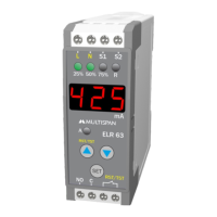
The Earth Leakage Relay ELR-63 is a sophisticated device designed for monitoring earth leakage currents in various electrical systems. It is suitable for use in 1-phase 2-wire, 3-phase 3-wire, and 3-phase 4-wire systems, offering broad applicability across different power configurations. The primary function of this relay is to detect and indicate earth leakage currents, providing crucial safety monitoring for electrical installations.
One of the key usage features of the ELR-63 is its intuitive display and control interface. It incorporates a 3-digit, 7-segment, 0.36-inch red display that clearly shows the actual value of the earth leakage current. This allows for quick and easy visual assessment of the system's status. The device is equipped with SET, INC (increment), and DEC (decrement) keys, which facilitate navigation through parameters and adjustment of settings.
The relay offers a comprehensive set of operational modes and parameter settings. Users can easily enter the parameter setting mode to configure various aspects of the device's behavior. A test mode is also available, allowing for verification of the relay's functionality without disrupting the main system. This is particularly useful for routine checks and troubleshooting.
A notable feature is the auto/manual tripping reset facility. This provides flexibility in how the relay responds after a trip event. In auto-reset mode, the relay can automatically reset once the earth leakage current falls below a predefined setpoint, provided the healthy condition relay mode is active. This can be beneficial in scenarios where temporary faults are expected to clear on their own. For situations requiring manual intervention, the manual reset option ensures that the system is only re-energized after a thorough inspection and rectification of the fault. The reset function can be activated either via a short press on the RST/TST pin or by pressing a key for a specified duration, offering multiple ways to restore operation.
The ELR-63 also includes LED indications for different levels of leakage current, enhancing its usability. There are LEDs for 25%, 50%, and 75% of the set leakage current. These LEDs blink when the current is within a certain range (e.g., 20% to <25% for the 25% LED) and illuminate continuously when the current reaches or exceeds the respective threshold. This visual feedback provides an immediate understanding of the severity of the leakage current, allowing operators to take prompt action. An additional "AMP" LED illuminates when the leakage current exceeds 999 mA, indicating a higher current range. A dedicated relay LED indicates the ON/OFF status of the control output, providing clear feedback on the relay's operational state.
Parameter setting is a straightforward process. Users can set the desired leakage current, which can range from 30mA to 3Amp. A delay time can also be configured, ranging from 0.00 to 9.99 seconds, to prevent nuisance tripping from transient events. The trip setting allows selection between 75% or 100% of the set point, providing flexibility in defining the trip threshold. The healthy condition relay mode can be set to ON/OFF, influencing the auto-reset behavior. Furthermore, the device supports an auto/manual reset mode, allowing users to choose their preferred reset method. A hysteresis value, adjustable from 0.00 to 2.99 Amp, can be set to prevent rapid cycling of the relay when the leakage current hovers around the setpoint. Access to these parameters is protected by a password, ensuring that only authorized personnel can modify critical settings.
For mechanical installation, the ELR-63 is designed for DIN rail mounting. The installation process involves raising a clamp at the back of the instrument, placing it on the DIN rail, and then releasing the clamp to secure it. Proper fitting is ensured by pulling the instrument outwards. Removal is equally simple, requiring the clamp to be raised. It is crucial to ensure that the equipment is not installed in close proximity to heating sources, caustic vapors, oil steam, or other unwanted process byproducts, as these can affect its performance and longevity. Unused terminals should not be connected to anything.
Maintenance of the ELR-63 is relatively simple, focusing on keeping the device clean and free from obstructions. Regular cleaning of the equipment is recommended to prevent blockage of ventilating parts, which could lead to overheating and impaired performance. A clean, soft cloth should be used for cleaning; isopropyl alcohol or any other cleaning agent should be avoided as they might damage the device. It is also explicitly stated that the fusible resistor should not be replaced by the operator, indicating that such tasks should be handled by qualified service personnel.
Safety precautions are paramount when operating and installing the ELR-63. Users are warned about the risk of electric shock, and it is emphasized that the power supply to the equipment must be kept OFF during wiring to prevent accidents. Touching terminals while power is supplied is strictly prohibited. To minimize electromagnetic interference, it is recommended to use wires with adequate rating and twists of the same size, with the shortest possible connections. Cables used for power connection should have a cross-section of at least 1mm and an insulation capacity of at least 1.5kV. When extending thermocouple lead wires, specific compensation wires should be used, and for RTD type, wiring material with low lead resistance and no resistance differentials among three wires is necessary. Using standard power supply cables is advised for better anti-noise effects.
During installation, care must be taken to prevent metal pieces, wire clippings, or fine metallic fillings from entering the product, as this could lead to safety hazards. A circuit breaker or mains switch must be installed between the power source and the supply terminal to facilitate easy power ON/OFF, and it should be conveniently accessible to the operator. The instrument should be used and stored within the specified ambient temperature and humidity ranges to ensure optimal performance and longevity. All safety-related codifications, symbols, and instructions in the manual must be strictly followed to ensure the safety of operating personnel and the instrument. Improper handling of the equipment, not in accordance with manufacturer specifications, may impair the protection provided by the equipment. Users are advised to read the complete instructions prior to installation and operation.
| Contact Arrangement | 2C |
|---|---|
| Mounting Type | PCB Mount |
| Contact Form | DPDT |
| Coil Power Consumption | 0.9W |
| Operate Time | 15ms |
| Insulation Resistance | 1000MΩ min @ 500V DC |
| Vibration Resistance | 10-55Hz, 1.5mm |
| Shock Resistance | 10G |