Do you have a question about the MULTISPAN VPR-22 and is the answer not in the manual?
Indicates under voltage, over voltage, phase sequence, phase asymmetry, and phase loss.
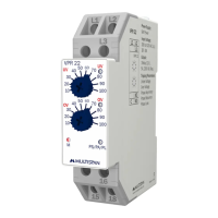
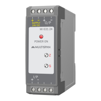
Adjustable knob for setting the under voltage threshold.
Adjustable knob for setting the over voltage threshold.
Visualizes the power supply status of the relay.
Illustrates the wiring for L1, L2, L3, and output terminals 15, 16, 18.
Details self-powered operation and input voltage range of 280-520V AC.
Describes the relay output: 1C/O, 5A, 230V AC resistive load.
Specifies trip delay, power ON delay, and asymmetry delay times.
Defines the meaning of RED (PL), Blinking Red (PA), Yellow (PS) LEDs.
Lists functions like phase loss, phase asymmetry, hysteresis, and rated voltage.
Graphical representation of over/under voltage, phase loss, and asymmetry.
Illustrates trip delay (T) and power ON delay (TP) in relation to functions.
Provides the physical measurements of the relay in millimeters.
Emphasizes following manual instructions for safe operation and handling.
Highlights the risk of electric shock and necessary precautions during wiring.
Guidelines for panel mounting, avoiding metallic debris, and switch placement.
Steps for installing on a DIN rail, ensuring proper fit, and removal.
Advice on avoiding proximity to heat sources and not using unused terminals.
The Multispan VPR-22 is a voltage protection relay designed to safeguard electrical systems from various voltage anomalies. This device continuously monitors the input voltage across three phases (L1, L2, L3) and provides robust protection against conditions that could harm connected equipment. Its primary function is to detect and react to under voltage, over voltage, phase asymmetry, phase sequence errors, and phase loss, ensuring the operational integrity and longevity of machinery.
The relay operates on a self-powered principle, drawing its operational energy directly from the monitored input voltage. This eliminates the need for a separate power supply, simplifying installation and reducing potential points of failure. The VPR-22 is equipped with a single relay output, which can be configured as a normally open (NO) or normally closed (NC) contact. This output is rated for a resistive load, making it suitable for controlling contactors, alarms, or other protective devices within a control circuit. When a voltage anomaly is detected, the relay output changes state, triggering the appropriate protective action, such as shutting down the affected equipment or activating an alarm.
A key feature of the VPR-22 is its intuitive user interface, which includes dedicated knobs for setting under voltage and over voltage trip thresholds. These knobs allow users to precisely define the acceptable voltage range for their specific application, providing flexibility and adaptability to different electrical environments. The device also incorporates a series of LED indicators that provide clear visual feedback on its operational status and any detected faults. A main LED indicates the power supply status, while a "FAULT INDICATION LED" illuminates to signal specific issues such as under voltage, over voltage, phase sequence errors, phase asymmetry, or phase loss. This immediate visual feedback helps operators quickly identify the nature of a problem, facilitating faster troubleshooting and resolution.
The VPR-22's tripping parameters are meticulously designed to offer comprehensive protection. It monitors for under voltage conditions, where the voltage drops below a user-defined threshold, and over voltage conditions, where the voltage exceeds a set limit. Phase asymmetry detection ensures that the voltage levels across the three phases remain balanced within acceptable limits, preventing damage to three-phase motors and other sensitive equipment. The device also checks for correct phase sequence, which is crucial for the proper operation of rotating machinery, preventing reverse rotation that could lead to mechanical damage or operational hazards. Furthermore, the VPR-22 detects phase loss, a critical condition where one or more phases are completely absent, which can cause severe damage to three-phase loads.
The relay incorporates delay times for various functions to prevent nuisance tripping due to transient voltage fluctuations. A "Trip Delay" ensures that the relay only activates after a sustained fault condition, while a "Power ON Delay" provides a brief period after power restoration before the relay engages, allowing the system to stabilize. Specific delays are also implemented for phase sequence/phase loss and asymmetry detection, further enhancing the reliability of the protection scheme. Hysteresis is built into the voltage monitoring functions, preventing rapid cycling of the relay when the voltage hovers near a trip threshold, thereby extending the lifespan of the relay and the controlled equipment.
Installation of the VPR-22 is designed to be straightforward and secure. It is a DIN rail-mountable device, allowing for easy integration into control panels. The terminal connections are clearly labeled for L1, L2, L3, and the relay output contacts (NO, C, NC), ensuring correct wiring. The compact dimensions of the device minimize the space required within a control panel, making it suitable for applications where panel space is at a premium.
Maintenance of the VPR-22 is minimal due to its robust design and self-powered operation. Regular visual inspection of the LED indicators can help in monitoring the system's health. In the event of a fault, the specific fault indication LED guides the user to the nature of the problem, simplifying diagnostic efforts. The device is built to withstand industrial environments, contributing to its long-term reliability. Safety precautions are emphasized throughout the manual, advising users to disconnect power before wiring and to use appropriate wiring practices to ensure safe operation and prevent electric shock. The design also considers electromagnetic interference, recommending proper wiring techniques to maintain signal integrity and device performance.
In summary, the Multispan VPR-22 is a comprehensive and reliable voltage protection relay that offers essential safeguarding for electrical systems. Its self-powered operation, user-friendly interface with adjustable thresholds, clear LED fault indications, and robust protection features against a wide range of voltage anomalies make it an invaluable component for ensuring the safety, efficiency, and longevity of industrial and commercial electrical installations.
| Contact Form | DPDT |
|---|---|
| Coil Voltage | 12VDC |
| Mounting Type | PCB |
| Operate Time | 10ms |
| Release Time | 5ms |
| Vibration Resistance | 10-55Hz, 1.5mm |