Device Description: Single Phase Voltage Relay SVR-22
The SVR-22 is a single-phase voltage relay designed to monitor and protect electrical systems from under-voltage and over-voltage conditions. This self-powered device provides essential fault indication and control functions, making it a crucial component for ensuring the stability and safety of electrical loads.
Function Description
The primary function of the SVR-22 is to continuously monitor the input voltage and trigger a relay output if the voltage falls outside a user-defined acceptable range. It incorporates separate knobs for setting the under-voltage (UV) and over-voltage (OV) tripping parameters, allowing for precise configuration based on the specific requirements of the connected load.
Key functional elements include:
- Voltage Monitoring: The device constantly measures the line-to-neutral (L-N) voltage within its specified input range.
- Under-Voltage Protection: Users can set a lower voltage threshold using the "UNDER VOLTAGE KNOB." If the input voltage drops below this set point, the device will detect an under-voltage fault.
- Over-Voltage Protection: Similarly, an upper voltage threshold can be set using the "OVER VOLTAGE KNOB." If the input voltage exceeds this set point, an over-voltage fault will be detected.
- Fault Indication: Dedicated LEDs provide visual feedback for fault conditions. A "FAULT INDICATION LED" illuminates for both under-voltage and over-voltage events.
- Power Supply Status: A "MAIN LED" indicates the power supply status, confirming that the device is operational.
- Relay Output: The device features a 1 Relay 1C/O (Changeover) output, which can be used to control external circuits, such as tripping a circuit breaker or activating an alarm, when a voltage fault is detected.
- Hysteresis: A fixed hysteresis of 6V is incorporated into the tripping mechanism. This prevents rapid cycling of the relay when the voltage hovers near the set point, ensuring stable operation.
- Auto Reset: The SVR-22 is equipped with an auto-reset function, meaning the relay will automatically return to its normal state once the voltage returns within the acceptable range after a fault.
- Delay Times: To prevent nuisance tripping from momentary voltage fluctuations, the device includes configurable delay times:
- Trip Delay: A 5-second delay before the relay trips after a fault is detected.
- Power ON Delay: A 5-second delay upon power-up before the device begins monitoring, allowing the system to stabilize.
Important Technical Specifications
The SVR-22 is designed for robust performance in various industrial and commercial applications.
- Power Supply: Self-powered, eliminating the need for an external power source for the device itself.
- Input Voltage: Operates within a broad range of 160 to 300V AC (Line-Neutral), suitable for single-phase, 2-wire systems with a frequency of 50/60Hz.
- Output:
- Relay Type: 1 Changeover (1C/O) relay.
- Current Rating: 5A.
- Voltage Rating: 230V AC.
- Load Type: Resistive load.
- Tripping Parameters:
- Under Voltage: Adjustable via a knob.
- Over Voltage: Adjustable via a knob.
- Hysteresis: Fixed at 6V.
- Delay Times:
- Trip Delay: 5 seconds.
- Power ON Delay: 5 seconds.
- Dimensions:
- Height: 90.00 mm
- Width: 22.5 mm
- Depth: 66.35 mm (excluding terminals)
- Mounting: DIN rail mountable.
Usage Features
The SVR-22 is designed for ease of use and clear indication of its operational status.
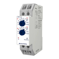
- User-Friendly Adjustment: Dedicated knobs for under-voltage and over-voltage settings allow for straightforward configuration without complex programming.
- Clear LED Indication:
- OV (Over Voltage) LED: Illuminates when an over-voltage condition is detected.
- UV (Under Voltage) LED: Illuminates when an under-voltage condition is detected.
- OV & UV LED OFF: Indicates a healthy voltage condition (within the set limits).
- MAIN LED: Confirms the device is powered and operational.
- Terminal Connections: Clearly labeled terminals (L, N, 15, 16, 18) facilitate easy and correct wiring. Terminals 15 (Common), 16 (Normally Closed), and 18 (Normally Open) provide flexible relay output connections.
- DIN Rail Mounting: The device is designed for quick and secure installation on a standard DIN rail, simplifying integration into control panels. The clamp mechanism allows for easy installation and removal.
- Control Function Graph: A detailed control function graph illustrates the device's behavior, showing how the relay output changes in response to voltage fluctuations, including the effects of hysteresis and delay times (TPON for Power ON Delay and T for Trip Delay). This visual aid helps users understand the operational logic.
Maintenance Features
While the SVR-22 is a robust device, proper installation and adherence to safety guidelines are crucial for its longevity and reliable operation.
- Self-Powered Design: Reduces complexity and potential points of failure associated with external power supplies.
- Robust Construction: Designed for industrial environments, ensuring durability.
- Safety Precautions: The manual emphasizes critical safety guidelines to prevent electric shock and ensure safe operation. These include:
- Disconnecting power before wiring.
- Avoiding contact with terminals when power is supplied.
- Using appropriately rated and twisted wires to reduce electromagnetic interference.
- Ensuring power source cables have a cross-section of at least 1mm and insulation capacity of at least 1.5kV.
- Using standard power supply cables for better anti-noise effects.
- Installation Guidelines: Provides clear instructions for mechanical and electrical installation, including:
- Ensuring the device is part of a main control panel where terminals are not accessible to end-users after installation.
- Preventing metallic debris from entering the product.
- Installing a circuit breaker or mains switch for power ON/OFF functionality in an easily accessible location.
- Operating and storing the instrument within specified ambient temperature and humidity ranges.
- Proper DIN rail mounting and removal procedures.
- Avoiding proximity to heating sources, caustic vapors, or oil steam.
- Not connecting anything to unused terminals.
By following these guidelines, users can ensure the SVR-22 operates effectively and safely, providing reliable voltage protection for their electrical systems. The device's auto-reset function also minimizes the need for manual intervention after a transient fault, contributing to reduced maintenance effort.