Do you have a question about the MULTISPAN UTR-1244 and is the answer not in the manual?
Details auxiliary supply voltage, power consumption, operating temperature, and humidity ranges.
Specifies input signal types, time ranges, display characteristics, key functions, and relay output ratings.
Outlines unit dimensions, panel cutout, operating modes, counting direction, and reset options.
Provides diagrams for mechanical installation, panel cutout, and terminal connections.
Offers guidelines for proper installation, wiring, and environmental considerations for the timer.
Emphasizes strict adherence to safety instructions, symbols, and precautions for operator and instrument safety.
Details critical steps to prevent electric shock during wiring, including keeping power off and using insulated wires.
Explains the operation of the Sequential Timer with timing diagrams for Relay 1 and Relay 2.
Details the Forward Reverse Timer operation, including forward, stop, and reverse time settings.
Describes the Combination Timer operation with delay and on-times for Relay 1 and Relay 2 across cycles.
Illustrates the Cyclic Timer operation for both 'cyclic on' and 'cyclic off' modes with timing diagrams.
Guides setting parameters like Process Time, Total Time, Stop Time, and Reverse Time for FRT.
Details setting parameters for SEQ, including Process Time, Set Time, Delay Time, and On Time for Relays.
Explains setting Process Time, Set Time, On Time, and Off Time for Cyclic Timer operation.
Covers setting parameters for Combination Timer, including delay times, relay on-times, and cycle counts.
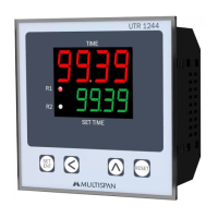
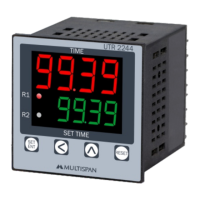
This universal timer, model UTR-1244, is a versatile device designed for precise time control in various industrial and commercial applications. It offers multiple operating modes, including Forward-Reverse Timer, Cyclic Timer, Sequential Timer, and Combination Timer, making it adaptable to a wide range of timing requirements.
The device features a clear display with an upper 4-digit, 7-segment red display for primary readings and a lower 4-digit, 7-segment green display for secondary information or settings. User interaction is facilitated through dedicated keys: SET/ENT, SHIFT, INC, and RESET, allowing for intuitive navigation and parameter adjustment.
The UTR-1244 operates as a universal timer, capable of managing time-based processes with high accuracy. Its core functionality revolves around controlling two independent relays (Relay 1 and Relay 2), each with a 1 C/O (NO-C-NC) configuration and a rating of 5A at 230V AC. The timer supports various time ranges, including seconds (9.999/999.9/9999), minutes (99.59/999.9/9999), and hours (99.59/999.9/9999), providing flexibility for short-duration events or extended operations.
Input for initiating timing sequences can be provided via NPN/PNP proximity sensors, micro switches, or limit switches, offering compatibility with different control systems. The counting direction can be set to either UP or DOWN, depending on the application's needs. Reset options include a front panel reset or a terminal reset, allowing for convenient control over the timing cycle.
Forward-Reverse Timer (FRT): This mode is ideal for applications requiring alternating forward and reverse operations, such as motor control. Users can set the forward time (Frtm), stop time (Sttm), and reverse time (rvtm). The total time (totl) for one complete cycle is also displayed. The device allows for setting the unit (seconds/minutes) and range for both forward and reverse times.
Sequential Timer (SEQ): In this mode, the timer executes a sequence of operations for Relay 1 and Relay 2. For each relay, users can define a delay time (dL), an on-time (on), and an off-time (of). The "cyc" parameter specifies the total number of repeat cycles for the entire sequence involving both relays. This mode is suitable for processes that require a specific order of events with defined durations.
Cyclic Timer (CYL): This mode enables repetitive on/off cycles. Users can configure the "ontm" (on time) and "oftm" (off time) for the relays. The "cycn" parameter allows selection between "cyclic on" and "cyclic off" operations, determining whether the cycle starts with the relay in an ON or OFF state. The total number of repeat cycles can also be set. This is useful for periodic tasks like pump control or lighting systems.
Combination Timer (COMB): This advanced mode allows for complex timing sequences by combining multiple cycles for each relay. For Relay 1, users can set delay times (d1c1, d1c2) and on-times (r1c1, r1c2) for two distinct cycles. Similarly, for Relay 2, delay times (d2c1, d2c2) and on-times (r2c1, r2c2) can be configured for two cycles. The "Cyc1" and "Cyc2" parameters define the number of combinations for Relay 1 and Relay 2, respectively. The "nocl" parameter specifies the total number of Relay-1 and Relay-2 combinations. This mode is suitable for intricate processes requiring synchronized or staggered operations of multiple outputs.
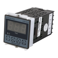
The UTR-1244 is designed for easy integration into existing control panels. It is a built-in type equipment, meaning its terminals are not accessible to the end-user after installation and internal wiring, enhancing safety. The device's compact dimensions (96x96x52 mm) and standard panel cutout (92x92 mm) ensure compatibility with common industrial enclosures.
For parameter setting, the device enters a dedicated mode by pressing and holding the SET key along with powering on the device. This allows users to configure the operating mode and various timing parameters. A password protection feature (default "25") is available to prevent unauthorized changes to detailed parameters.
The status LED indicators provide visual feedback on the control output of Relay 1 and Relay 2, allowing for quick monitoring of their operational status. The device also includes a "Memory Retain" feature, which can be enabled or disabled, to preserve settings during power interruptions. The "Start Pulse" option allows configuration of how the timer initiates, whether by power on, trigger, or enable signal.
Proper installation is crucial for the safe and reliable operation of the UTR-1244. The panel cutout should match the specified dimensions. The unit must be fitted into the panel using the provided clamps. It is important to ensure that the equipment is not installed near heat sources, caustic vapors, oils, steam, or other process byproducts.
Wiring should be done using specified crimp terminals (M3.5 screws) with a tightening torque of 1.2 N.m. Unused terminals should not be connected. A circuit breaker or mains switch must be installed between the power source and the supply terminal for easy power ON/OFF control, and it should be conveniently accessible. To minimize electromagnetic interference, adequate wire rating and twists of equal size should be used, with the shortest possible connections. The power supply cable should have a cross-section of 1mm² or greater and insulation capacity of at least 1.5kV.
Maintaining the UTR-1244 is straightforward and essential for its longevity and performance. Regular cleaning of the equipment is recommended to prevent blockage of ventilating parts, which could lead to overheating. The device should be cleaned with a clean, soft cloth. It is important to avoid using isopropyl alcohol or any other harsh cleaning agents, as these can damage the unit. The fusible resistor, a critical component, must not be replaced by the operator; any issues with this part should be addressed by qualified service personnel.
All safety-related codifications, symbols, and instructions in the operating manual and on the equipment must be strictly followed to ensure the safety of personnel and the instrument. Failure to handle the equipment as specified by the manufacturer may impair the provided protection. Users must read the complete instructions prior to installation and operation. A warning symbol indicates a "Risk of electric shock."
To prevent electric shock, the power supply to the equipment must be turned OFF during wiring. Terminals should not be touched while power is supplied. Using a standard power supply cable for the instrument can enhance anti-noise effects.
| Supply voltage | 24-240 VAC/DC |
|---|---|
| Power consumption | 3VA |
| Number of outputs | 2 |
| Output type | Relay |
| Mounting | Panel mount |
| Timing ranges | 0.1 s - 999 h |
| Repeat accuracy | ±0.5% |
| Ambient operating temperature | -10°C to 55°C |
| Storage temperature | -25°C to +70°C |
| Dimensions | 48 x 48 x 48 mm |
| Protection class | IP20 |
| Operating modes | On-delay, Off-delay, Interval |