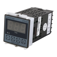
UTR-4244
AUXILIARY SUPPLY:
UNIVERSAL TIMER
Supply voltage
Power consumption
(VA RATING)
Approx 4 VA @ 230V AC MAX
ENVIRONMENT CONDITION:
Relative Humidity
Protection Level
(AS Per Request)
Operating Temp.
0°C to 55°C
UP to 95% RH
(non-condensing)
IP-65 (Front side) As per IS/IEC
60529 : 2001
100 to 250V AC, 50-60Hz
MECHANICAL INSTALLATION GUIDELINES
1. Prepare the panel cutout with proper dimensions as shown
above.
2. Fit the unit into the panel with the help of clamp given.
3. The equipment in its installed state must not come in close
proximity to any heating source, caustic vapors, oils steam,
or other unwanted process byproducts.
4. Use the specified size of crimp terminal (M3.5 screws) to
wire the terminal block. Tightening the screws on the
terminal block using the tightening torque of the range of
1.2 N.m.
5. Do not connect anything to unused terminals.
INSTALLATION GUIDELINES
1. This equipment, being built-in-type, normally becomes a
part of main control panel and in such case the terminals
do not remain accessible to the end user after installation
and internal wiring.
2. Do not allow pieces of metal, wire clippings, or fine metallic
fillings from installation to enter the product or else it may
lead to a safety hazard that may in turn endanger life or
cause electrical shock to the operator.
3. Circuit breaker or mains switch must be installed between
power source and supply terminal to facilitate power ‘ON’ or
‘OFF’ function. However this mains switch or circuit breaker
must be installed at convenient place normally accessible to
the operator.
4. Use and store the instrument within the specified ambient
temperature and humidity ranges as mentioned in this
manual.
Page -1
MAINTENANCE
1. The equipment should be cleaned regularly to avoid
blockage of ventilating parts.
2. Clean the equipment with a clean soft cloth. Do not use
isopropyl alcohol or any other cleaning agent.
3. Fusible resistor must not be replaced by operator.
Read complete instructions prior to installation
and operation of the unit.
WARNING : Risk of electric shock.
SAFETY PRECAUTION
!
All safety related codifications, symbols and instructions
that appear in this operating manual or on the equipment
must be strictly followed to ensure the safety of the operating
personnel as well as the instrument.
If all the equipment is not handled in a manner specified
by the manufacturer, it might impair the protection provided
by the equipment.
WARNING GUIDELINES
WARNING : Risk of electric shock.
1. To prevent the risk of electric shock, power supply to the
equipment must be kept OFF while doing the wiring
arrangement. Do not touch the terminals while power is
being supplied.
2. To reduce electro magnetic interference, use wire with
adequate rating and twists of the same of equal size shall
be made with shortest connection.
3. Cable used for connection to power source, must have a
cross section of 1mm or greater. These wires should have
insulations capacity made of at least 1.5kV.
4. A better anti-noise effect can be expected by using
standard power supply cable for the instrument.
Input (Start Pulse)
Time Range
Display
Operating Mode
Size
Keys
Counting Direction
Panel Cutout
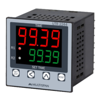
Upper: 4 digit, 7 segment, 0.56” Red
Forward - Reverse Timer
Lower: 4 digit, 7 segment, 0.33” Green
48 (H) x 48 (W) x 90 (D) mm
SET/ENT, SHIFT, INC, RESET
44 (H) x 44 (W) mm
TECHNICAL SPECIFICATION
GENERAL SPECIFICATION:
DISPLAY AND KEYS:
DIMENSION:
MECHANICAL INSTALLATION
TERMINAL CONNECTION
1 - Relay 1 control output
2 - Relay 2 control Output
STATUS LED DESCRIPTION
KEY OPERATION
To enter in parameter setting
mode
To reset the timer
PRESS KEYFUNCTION
OPERATOR MODE
PARAMETER SETTING MODE
Edited parameter value to be set,
And move to the next parameter
It will select the digit to modify,
When value is edited
It will change the Value of
selected digit
Page -2
NPN/PNP Proximity
Sec (9.999/999.9/9999)
Micro Switch
Min (99.59/999.9/9999)
Limit Switch
Hour (99.59/999.9/9999)
Cyclic Timer
Sequential Timer
Combination Timer
UP/ DOWN
Reset Option
Front Panel Reset
Terminal Reset
48
44
44
48
Outline Dimension (mm)
Panel Cutout
Dimension (mm)
Press Key along
with power on device
RESET
SEQUENTIAL TIMER
OPERATING MODE FUNCTION
Start pulse
Start pulse
COMBINATION TIMER
dL-1
d1c1
dL-2
Of-1
d1c2
Of-2
on-1
r1c1
on-2
5
5
5
5
10
10
10
10
15
15
15
15
20
20
20
20
25
25
25
25
30
30
30
30
35
35
35
35
40
40
40
40
45
45
45
45
50
50
50
50
55
55
55
55
60
60
60
60 65
70
Relay-1
Relay-1
Relay-2
Relay-2
Relay-1 setting
Relay-1 setting
dL-1(Delay time )= 5 sec
d1c1(Delay Time Of Relay 1 & cycle 1)= 5 sec
dL-2(Delay time)= 10 sec
d2c1(Delay Time Of Relay 2 & cycle 1)= 5 sec
of-1(Off time)= 5 sec
d1c2(Delay Time Of Relay 1 & cycle 2)= 5 sec
r1c2(Relay on time Of Relay 2) = 10 sec1 & cycle-
Cyc1(Relay combination) = 2 1
Cyc2(Relay combination) = 2 2
of-2(Off time)= 10 sec
d2c2(Delay Time Of Relay 2 & cycle 2)= 10 sec
r2c2(Relay on time Of Relay 2) = 10 sec2& cycle-
on-1(On time )= 10 sec
r1c1(Relay on time Of Relay 1 )=10 sec& cycle-1
on-2(On time)= 20 sec
r2c1(Relay on time Of Relay )= 10 sec 2& cycle-1
Relay-2 setting
Relay-2 setting
cyc(Total no. of repeat cycle of Relay 1 & Relay 2)= 1
nocl( )=2 Total no. of Relay-1 & Relay-2 Combination
d1c1
d1c2
r1c2 r1c1
r1c2
Time(Sec)
Time(Sec)
r2c1
d2c1
d2c2
r2c2
r2c1
d2c1
r2c2
d2c2
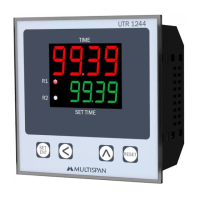
TIME
SET TIME
9939
9939
1
2
FORWORD REVERSE TIMER
Start pulse
cyclic on
cyclic off
CYCLIC TIMER
on time (ontm)= 5 sec
off time (oftm)= 10 sec
Reverse time
sttm
sttm
sttm
sttm
sttm
sttm
sttm
sttm
50
50
10
10
15
15
20
20
25
25
25
25
25
20
20
20
20
15
15
15
15
10
10
10
10
5
5
5
5
25
30
30
30
30
30
30
35
35
40
40
45
45
50
50
55
55
60
60
Relay-1
Relay-1Relay-2Relay-1Relay-2
Relay-2
Forword Time (Frtm) = 10 SeC
Stop Time (Sttm) = 5 Sec
Total Time (totl) = 1 min
Reverse Time (rvtm) = 10 Sec
on time
off time
off time
on time
off time
off time
on time
on time
Time(Sec)
Time(Sec)
Time(Sec)
Time(Sec)
Forward time
Time
(sec)
Time
(sec)
Forward time
Reverse time
Time(Sec)
Time(Sec)
ontm
ontm ontm
ontm
oftm
oftm
oftm
oftm
This symbol in all graph
will represent Relay is On
-
INPUT SPECIFICATION:
OUTPUT SPECIFICATION:
Relay
Relay Type
Rating
2 nos.
1 C/O (NO-C-NC)
5A, 230V AC
Relay Output
90
300.0
300.0
.
Made in India
www.multispanindia.com
1
2
3
4
5
+12V
I/P
M/S
GND
L
N
!
100
~
50/60 Hz
250V AC
4VA
PROXI NPN
8
9
10
C1
No1
RELAY-2
11
12
Nc1
No2
C2
RELAY-1
PROXY COLERS CODE
+12V
OUTPUT
GND
Brown
Black
Blue
Red Green Black
3