www.multispanindia.com
Page - 1UTR-413
Technical Specification
Connection Diagram
OPERATING MANUAL
UNIVERSAL TIMER
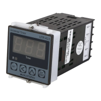
UTR-413
Output
Power Supply
Reset
Protection Level
Operating
Relative
(As per request)
Temperature
Humidity
1 relay, 2 C/O contact, 230V AC, 5A
100 to 250V AC, 50 / 60 Hz, Approx 4VA
Front key & Back Reset
IP-65(Front side) AS per IS/IEC 60529:2001
0°C To 55°C
Up to 95% RH Non Condensing
Model
Display
Size(HXWXD)
Panel Cutout
Input
45 X 45 mm
48 X 48 X 95 mm
3 Digit, 56”, 7 Segment LED
UTR 413
NPN Proximity & Micro Switch
Notes:
1). POWER ON : Timer starts counting as soon as it gets power supply.
2). By default Cycle ON Mode is provided. Please refer programming guide to change to Cycle OFF
Delay ON/ Delay OFF Mode.
3). Instrument can be Start and hold by front key, when it is in trigger pulse mode.
4). If we set cycle parameter 000 then the cycle timer will continue the cycle infinitely.
5). In enable pulse mode, if the memory parameter is selected YES and If the enable pulse is gone
& receive again before the set point, the timer will resume from the old value.
6). In enable pulse mode, if the memory parameter is selected NO and If the enable pulse is gone
& receive again before the set point, the timer will start 000.
1 2 3
UTR 413
SET
ENT
RESET
R
Time
START HOLD
!
100
250V AC
~
50/60 HZ
4VA
1
2
3
4
5
L
N
7
6
8
9
10
11
12
NC
RELAY
RESET
NC
C
NO
NO
M/S
PROXI NPN
I/P
+12V
GND
UTR 413
Made in India
www.multispanindia.com