The UNIVERSAL TIMER UTR-2033 is a versatile industrial timer designed for various control applications, offering a range of operating modes and precise timing capabilities.
Function Description
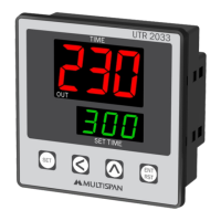
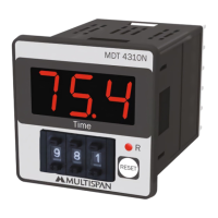
The UTR-2033 functions as a universal timer capable of operating in several modes: Cyclic On Timer, Cyclic Off Timer, Delay On Timer, and Delay Off Timer. It supports both UP and DOWN counting directions. The device features a dual-display system: an upper 3-digit, 7-segment, 0.80" display for process time and a lower 3-digit, 7-segment, 0.40" display for set time. Input for triggering the timer can be from NPN/PNP Proximity sensors or a Micro Switch. Output is provided via a single relay with two changeover (C/O) contacts. The timer allows for flexible reset options, including a front panel reset and a terminal reset. Parameter settings are protected by a password to prevent unauthorized changes.
Important Technical Specifications
- Auxiliary Supply:
- Voltage: 100 to 270V AC, 50-60Hz
- Power Consumption: Approximately 3 VA @ 230V AC MAX
- Input Specifications:
- Input (Start Pulse): NPN/PNP Proximity, Micro Switch
- Time Range:
- Seconds: 9.99 / 99.9 / 999
- Minutes: 9.59 / 99.9 / 999
- Hours: 9.59 / 99.9 / 999
- Output Specifications:
- Relay: 1 NO.
- Relay Type: 2 C/O (Changeover)
- Rating: 5A, 230V AC
- Environmental Conditions:
- Operating Temperature: 0°C to 55°C
- Relative Humidity: Up to 95% RH (non-condensing)
- Protection Level: IP-65 (Front side) as per IS/IEC 60529:2001
- Mechanical Specifications:
- Outline Dimension: 72 (H) x 72 (W) x 45 (D) mm
- Panel Cutout: 72 (H) x 72 (W) mm
- Display:
- Upper: 3 digit, 7 segment, 0.80" (Process Time)
- Lower: 3 digit, 7 segment, 0.40" (Set Time)
- Keys: SET, SHIFT, INC, ENT/RST
Usage Features
The UTR-2033 offers a user-friendly interface for setting parameters and monitoring operation.
- Key Operation:
SET key: Enters parameter setting mode, moves to the next parameter, saves and exits settings.SHIFT key: Selects the digit to modify when a value is edited.INC key: Changes the value of the selected digit.ENT/RST key: Saves and exits parameter settings, also functions as a reset.
- Operating Modes:
- Cyclic ON Timer: The relay turns ON for a set duration (ON Time 1), then OFF for another set duration (OFF Time 1), repeating for a specified number of cycles.
- Cyclic OFF Timer: The relay turns OFF for a set duration (OFF Time 1), then ON for another set duration (ON Time 1), repeating for a specified number of cycles.
- Delay ON Timer: The relay turns ON after a set delay time once the start pulse is received.
- Delay OFF Timer: The relay turns OFF after a set delay time once the start pulse is received.
- Parameter Setting:
- Access to parameter settings requires entering a password (default 25).
- Users can select the operating mode (Cyclic ON, Cyclic OFF, Delay OFF, Delay ON).
- For Cyclic modes, parameters include:
- Number of Repeat Cycles.
- Unit Selection for Cycle ON Time (Sec/Min/Hr).
- Range Selection for Cycle ON Time (9.99/99.9/999).
- Unit Selection for Cycle OFF Time (Sec/Min/Hr).
- Range Selection for Cycle OFF Time (9.99/99.9/999).
- For Delay modes, parameters include:
- Unit Selection for Delay Time (Sec/Min/Hr).
- Range Selection for Delay Time (9.99/99.9/999).
- Common parameters for all modes include:
- Time counting direction (UP Count/Down Count).
- Memory Retain (Yes/No) to preserve settings after power loss.
- Start Pulse configuration (Power ON/Trigger/Enable).
- Terminal Connection: Clearly labeled terminals for auxiliary supply (L, N), +12V, NPN I/P, PNP I/P, GND, RESET, and relay contacts (NC, C, NO for both relays). Micro Switch connection is specified for terminals 4 & 6.
- Status LED Description: An output indication LED is provided to show the current status of the timer.
Maintenance Features
The manual provides clear guidelines for installation and maintenance to ensure the longevity and safe operation of the device.
- Mechanical Installation Guidelines:
- Requires a panel cutout of specified dimensions.
- Secured with clamps.
- Must be kept away from heating sources, caustic vapors, oils, steam, or other unwanted process by-products.
- Wiring should use specified crimp terminals (M3.5 screws) with a tightening torque of 1.2 N.m.
- Unused terminals should not be connected.
- Electrical Installation Guidelines:
- Power supply must be OFF during wiring to prevent electric shock.
- Use appropriately rated and twisted wires to reduce electromagnetic interference.
- Cable for power source must have a cross-section of at least 1mm and insulation capacity of at least 1.5kV.
- Standard power supply cable is recommended for better anti-noise effect.
- A circuit breaker or mains switch must be installed between the power source and supply terminal for easy ON/OFF function, accessible to the operator.
- Prevent metal pieces or clippings from entering the product to avoid safety hazards.
- Safety Precautions:
- All safety codifications and symbols in the manual must be strictly followed.
- Improper handling may impair the protection provided by the equipment.
- Read complete instructions before installation and operation.
- Warning: Risk of electric shock.
- General Maintenance:
- Regular cleaning of the equipment is necessary to prevent blockage of ventilating parts.
- Clean with a soft, clean cloth; avoid isopropyl alcohol or other cleaning agents.
- The fusible resistor must not be replaced by the operator.
- Environmental Considerations: Use and store the instrument within the specified ambient temperature and humidity ranges.
The UTR-2033 is designed for robust performance in industrial environments, offering precise timing control and ease of integration into existing systems.