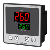
This document describes the UTR-1033 Universal Timer, a device manufactured by MULTISPAN.
Function Description
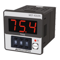
The UTR-1033 is a versatile universal timer designed for various industrial and commercial applications. It features a clear digital display for both the current time (or process time) and the set time, allowing users to easily monitor and configure timing operations. The timer supports multiple operating modes, including Cyclic ON, Cyclic OFF, Delay ON, and Delay OFF, making it adaptable to a wide range of timing requirements. It can be configured for either UP count or DOWN count timing direction. The device also includes a memory retain feature to preserve settings in case of power interruption and a start pulse option for initiating timing cycles.
Important Technical Specifications
Supply Voltage: The timer operates on a supply voltage of 100 to 270V AC, with a frequency of 50-60Hz.
Power Consumption: It has an approximate power consumption of 3 VA at 230V AC MAX.
Operating Temperature: The device is designed to operate in environments with temperatures ranging from 0°C to 55°C.
Relative Humidity: It can withstand relative humidity levels of up to 95% RH (non-condensing).
Protection Level: The UTR-1033 boasts an IP-65 (Front side) rating, indicating excellent protection against dust and water ingress from the front. It also meets IS/IEC 60529:2001 standards.
Output: The timer provides a relay output, with 1 normally open (NO) contact. The relay type is 2 C/O (Changeover), rated for 5A at 230V AC.
Time Range: The time range is highly flexible, allowing settings from 9.99 seconds up to 999 hours, 99 minutes, and 99 seconds (999.99.999). This broad range makes it suitable for both short-duration and long-duration timing tasks.
Input: The timer accepts an NPN/PNP proximity switch input or a micro switch input for starting the process.
Display: It features a 3-digit, 7-segment display for the upper value (current time) and a 3-digit, 7-segment display for the lower value (set time). The display color is red.
Keys: The device is equipped with SET, SHIFT, INC, ENT/RST keys for configuration and operation.
Dimensions: The physical dimensions of the timer are 96 (H) x 96 (W) x 43 (D) mm.
Panel Cutout: The required panel cutout for installation is 92 (H) x 92 (W) mm.
Usage Features
Operating Modes:
- Cyclic ON Timer: The output turns ON for a set duration, then OFF for another set duration, repeating the cycle.
- Cyclic OFF Timer: The output turns OFF for a set duration, then ON for another set duration, repeating the cycle.
- Delay ON Timer: The output turns ON after a set delay period once the input is triggered.
- Delay OFF Timer: The output turns OFF after a set delay period once the input is triggered.
Counting Direction: The timer supports both UP count and DOWN count timing directions, which can be selected by the user.
Reset Option: It includes a front panel reset button and a terminal reset option for convenience.
Parameter Setting:
- Entering Parameter Setting: To enter the parameter setting mode, the user presses and holds the SET key. A password (25) is required to access the settings.
- Selecting Operating Mode: Users can choose between Cyclic ON, Cyclic OFF, Delay ON, or Delay OFF modes.
- Setting Time Units: Time units (seconds, minutes, or hours) can be selected for both ON and OFF durations in cyclic modes, and for delay times in delay modes.
- Setting Time Values: The timer allows precise setting of time values within the specified range (e.g., 9.99 to 999.99.999).
- No. of Repeat Cycle: In cyclic modes, the number of repeat cycles can be configured.
- Memory Retain: This feature ensures that the timer's settings are saved even after a power outage. Users can enable or disable this function.
- Start Pulse: The start pulse can be configured as Power ON, Trigger, or Enable, determining how the timing cycle is initiated.
- Saving Settings: After making changes, pressing the SET key saves the settings and exits the parameter setting mode.
Key Operation:
- SET Key: Used to enter parameter setting mode, move to the next parameter, set a value, and save/exit.
- SHIFT Key: Used to select the digit to modify when a value is being edited.
- INC Key (Up Arrow): Used to increment the value of the selected digit.
- DEC Key (Down Arrow): Used to decrement the value of the selected digit.
- ENT/RST Key: Used to reset the timer.
Wiring: The manual provides a detailed wiring diagram, indicating terminals for supply voltage (L, N), relay output (NO, C, NC), and input (PNP, GND). It also specifies the use of a micro switch or M/S connection for inputs.
Installation Guidelines:
- The device should be mounted into a panel cutout with proper dimensions.
- Ensure the panel cutout is free from burrs and sharp edges.
- The unit should not be installed in areas with excessive heat, caustic vapors, oils, steam, or other unwanted process by-products.
- Use specified size of crimp terminal (M3.5 screws) to wire the terminal block, tightening the screws to the recommended torque range of 1.2 N.m.
- Do not connect anything to unused terminals.
- The device is a main control panel component and should be installed such that terminals are not accessible to the end user after installation.
- Do not allow pieces of metal, wire clippings, or fine metallic fillings to fall into the product during installation, as this may cause electrical shock.
- A circuit breaker or mains switch must be installed between the power source and the supply terminal to facilitate power ON/OFF.
- Store the instrument within the specified ambient temperature and humidity ranges as mentioned in the manual.
Maintenance Features
Cleaning:
- The equipment should be cleaned regularly to avoid blockages of ventilating parts.
- Clean the equipment with a clean soft cloth. Do not use isopropyl alcohol or any other cleaning agent.
Fuse Replacement:
- A fusible resistor must not be replaced by the operator.
Safety Precautions:
- Risk of Electric Shock: To prevent the risk of electric shock, ensure the supply to the equipment is kept OFF while doing the wiring arrangement. Do not touch the terminals while power is being supplied.
- EMI Reduction: To reduce electromagnetic interference, use wire with adequate rating and twists of the same or equal size as shall be made with shortest connection.
- Cable Sizing: For connection to power source, wires must have a cross section of 1mm² or greater. These wires should have insulation capacity marked at least 1.5kV.
- Anti-noise Effect: For better anti-noise effect, use a twisted supply power cable for the instrument.
- All safety-related codifications, symbols, and instructions in the manual must be strictly observed to ensure the safety of the operating personnel as well as the instrument.
- If the equipment is not handled in a manner specified by the manufacturer, it might impair the protection provided by the equipment.
- Read complete instructions prior to installation and operation of the unit.
The manufacturer reserves the right to make changes to specifications without notice for continuous process development. For updated information, users are advised to contact the manufacturer directly.