Do you have a question about the MUNIC C4D-4G4USAA V8+ and is the answer not in the manual?
Safety instructions for battery handling, replacement, and disposal.
Details on radio frequency exposure limits and compliance for the device.
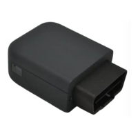
Visual identification of external components and connectors on the device.
Visual identification of internal components and their arrangement.
Detailed pinout configuration for the OBD connector.
Mapping of wire colors to OBD adapter pins.
Step-by-step guide for safely opening the device casing.
Instructions for properly reassembling the device after access.
Procedure for installing the dongle into the vehicle's OBD port.
The C4D-4G4USAA_V8+ is an OBD dongle designed for collecting and transmitting vehicle data. It integrates various communication and positioning technologies, making it suitable for a range of telematics applications. The device is compact and designed for easy installation into a vehicle's OBD connector.
The primary function of the C4D-4G4USAA_V8+ is to act as a vehicle data acquisition and transmission unit. It connects directly to the vehicle's On-Board Diagnostics (OBD) port, allowing it to read various vehicle parameters. The collected data can then be transmitted wirelessly using its integrated modem (4G Cat.4) and Wi-Fi capabilities. The device also includes GNSS (GPS, GLONASS) for location tracking and an accelerometer for motion detection. Its internal battery provides backup power, ensuring continuous operation even when the vehicle's ignition is off. The device features LED indicators to provide visual feedback on its operational status, including modem activity, GNSS fix, and power status.
Performance:
Power Supply:
Communication:
Positioning:
Interface & Telematics Features:
Environmental:
Dimensions:
The C4D-4G4USAA_V8+ is designed for straightforward use. Its primary usage involves connecting it to a vehicle's OBD connector. The device then automatically begins collecting data and communicating as configured.
LED Sequences: The device provides visual feedback through its two bicolor LEDs (Signal LED and Power LED).
OBD Adapter Wires: An optional OBD adapter cable is available for connecting the device to a computer (laptop/desktop) for configuration or diagnostics. The pin-out for this adapter is provided, detailing the wire colors for each OBD pin (e.g., Yellow for Pin 2, Black for Pin 4, Green for Pin 6, Red for Pin 16 for Battery voltage).
The device is designed for internal access for maintenance or SIM card insertion (if not using eSIM).
Opening the Device:
Closing the Device:
Battery Warning: The manual emphasizes critical battery safety warnings, including not disassembling, crushing, deforming, puncturing, or shredding the battery. It also warns against exposing the battery to water, fire, or explosion hazards. Only qualified charging systems and replacement batteries (IEEE 1725 standard) should be used to avoid risks. Battery replacement should only be performed by authorized service providers if it's not user-replaceable. Used batteries must be disposed of according to local regulations. Dropping the device or battery, especially on a hard surface, requires inspection by a service center.
FCC Regulations: The device complies with FCC Part 15 rules, ensuring it does not cause harmful interference and accepts received interference. Users are advised on measures to correct interference if it occurs (reorienting antenna, increasing separation, connecting to different circuit). Changes or modifications not expressly approved by the responsible party could void the user's authority to operate the equipment.
FCC RF Exposure Information (SAR): The device is designed to meet FCC emission limits for radio frequency (RF) energy. The highest reported SAR value for usage near the body is 1.34 W/kg, and for extremity usage, it is 3.30 W/kg. SAR compliance for body operation is based on a separation distance of 15 mm between the unit and the human body. The FCC has granted equipment authorization for this model, with SAR information available on www.fcc.gov/oet/ea/fccid under FCC ID: A6GC4D-4G4USV8.
| Brand | MUNIC |
|---|---|
| Model | C4D-4G4USAA V8+ |
| Category | Automobile Accessories |
| Language | English |