Section 15 00-02-0729
02-11-11 - 5 -
Typical Installation
Mounting the LM500
NOTE: Mount the LM500 as close as possible to the crankcase.
CAUTION: Excessive vibration can cause overfill. Be sure mounting brackets are
supported.
The following instructions are based on the use of the pipe and universal mounting brackets shown on page 1.
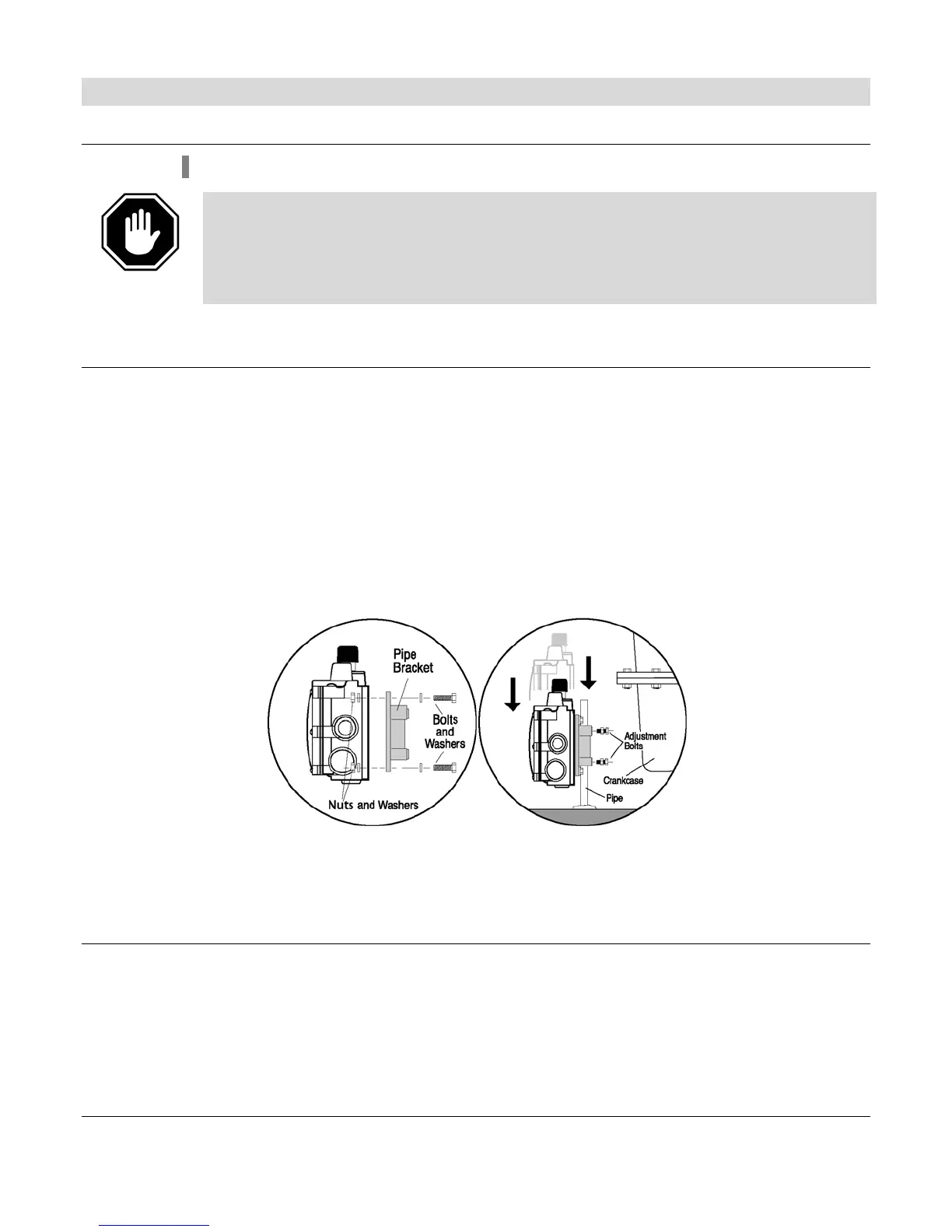
Pipe Bracket Mounting (PM) (P/N 15000518)
1. Mount a nominal 1/2in. (13mm) diameter pipe to the base of the engine.
2. Install the pipe bracket to the lM500 using two 1/4-20 UNC x 1 inch bolts; nuts and lock
washers supplied. See Figure 2A.
3. Slip the LM500 onto the pipe and install the two adjustment bolts. Each bolt consists of
a 1/4-20 UNC x 1in. bolt, nuts and lock washers. See Figure 2B. DO NOT tighten the
adjustment screws too tight as height adjustment might be needed later during the
operation. Refer to “Connecting Fittings and Hoses”, for more information regarding
height adjustment of the LM500 in alignment with the oil level in the crankcase.
Figure 2A Figure 2B
Universal Bracket Mounting (UB) (P/N 15000519)
The universal bracket has two mounting methods: base mounting or pan mounting.
Base Mounting
1. Install the universal bracket to the base as shown in Figure 3A using two split lock
washers and two 5/16 inch dia. Bolts or others a necessary.