Section 15 00-02-0729
02-11-11 - 2 -
Operating the Range of the Snap Switch
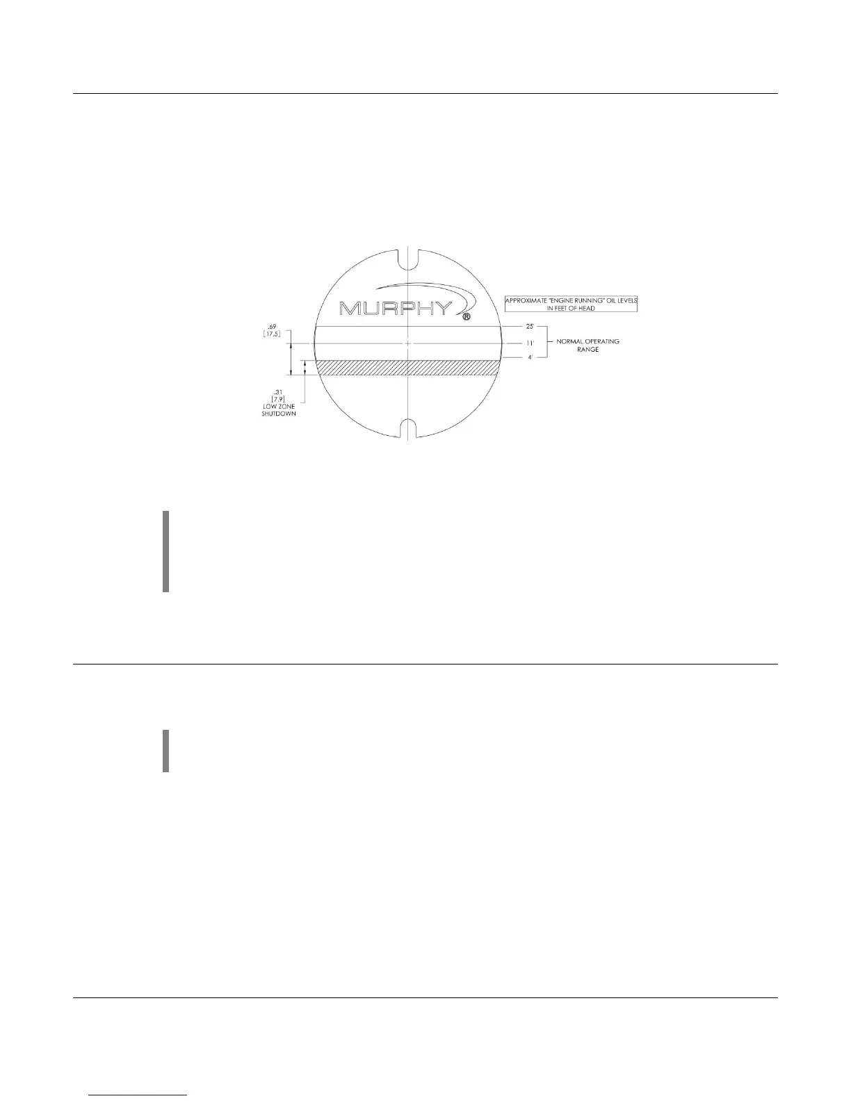
Figure 1 shows the LM500 dial and the operating range of the switch. If level is within the
designated zones, the switch will activate.
The switch activates approximately 1/4 in. (6 mm) from the bottom of the low zone. The dial-in
Figure 1 shows that if the level continues to drop into the low-low zone, a shutdown will occur.
Figure 1
NOTE: color zones on dial face show approximate normal operating
zones. Actual conditions may vary depending upon operating
characteristics of the engine. Placement of the LM500 according to the
above instructions will compensate for these conditions.
Test Feature
The form C (3-wire) contact allows a controller/enunciator to be wired as a closed loop
system, resulting in a reliable fault-sensitive circuit.
NOTE: Holding test button in for a prolonged period of time could cause
crank case to over fill.