Operating Manual
MSBA00049
Date: 21.03.2019
Rev.: 05
Page 8 of 14
Mütec Instruments GmbH Tel.: +49 (0) 4185-80 83-0 E-Mail: muetec@muetec.de
Bei den Kämpen 26 Fax: +49 (0) 4185-80 83-80 Web: www.muetec.de
D-21220 Seevetal-Ramelsloh
6 Mounting Instructions
6.1 Selection of the mounting position
The inlet and outflow zone for FS750E should not be
less than 3 times the nominal diameter.
After fixing the threaded sleeve in a 90° angle to the
tube axis, the mounted weld must close the gap
between the sleeve and the pipe wall reliably.
The quality of the weld can be tested with a
subsequent pressure test. The drilling of the tube wall
for the required measurement window is performed
with an 18 mm drill bit. Therefor the previously welded
sleeve serves as a drilling template. After drilling, the
borehole on the inner pipe wall needs to be trimmed
as much as possible to ensure that material deposits
cannot take place.
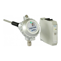
6.2 Sensor Mounting
For mounting sleeve need to be threaded on the tube
in a 90° angle to the tube axis
The length of the sensor rod should be at least 1/3 of
the inner diameter of the pipe. The sensor rod must
not come in contact with the opposite wall or with
other metallic parts. Therefore it is recommended to
keep a minimum distance of 20mm between the
opposite wall and the end of the sensor rod.
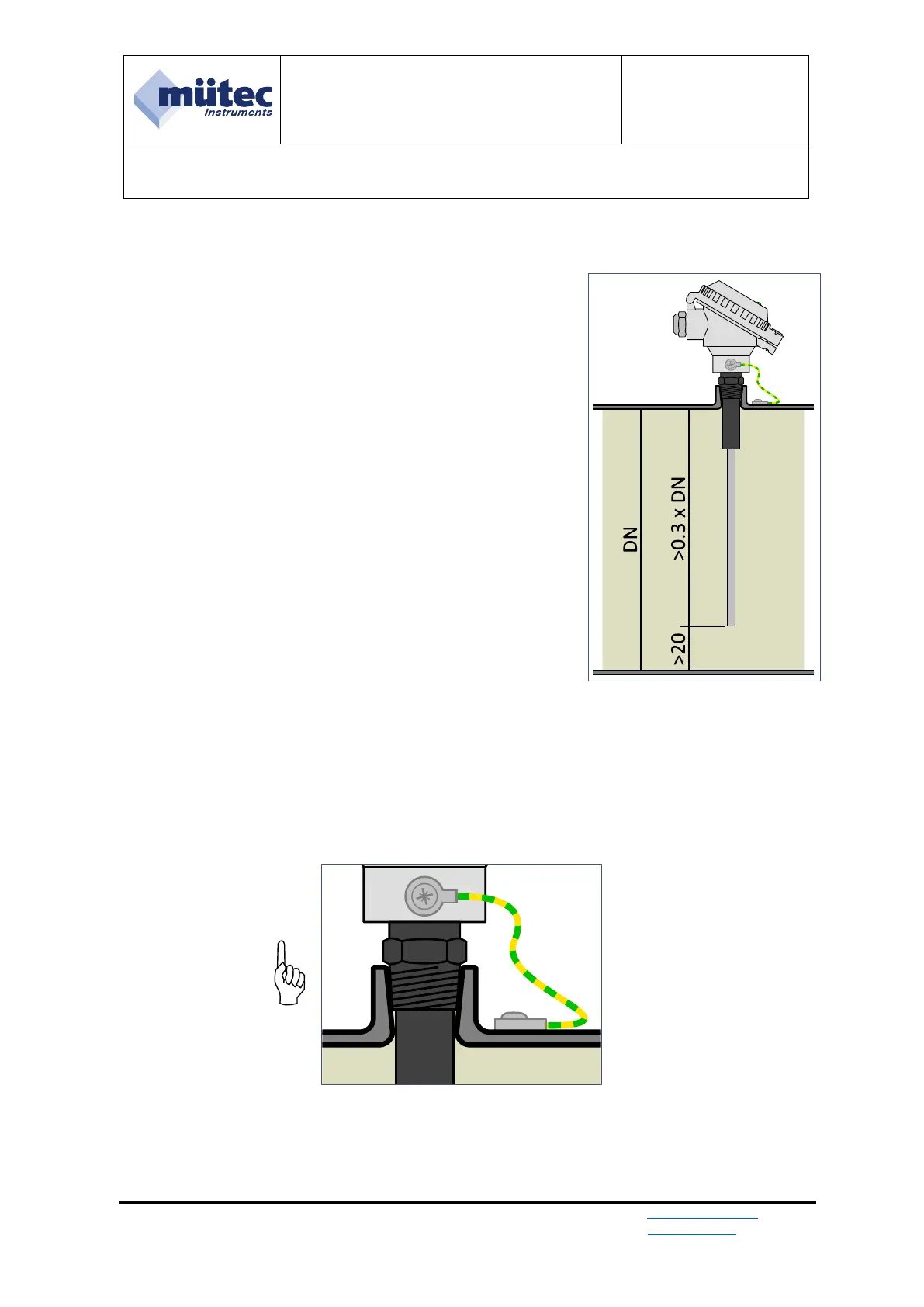
For proper device operation it is mandatory, to establish the earthing
connection between the sensor enclosure and the installation location (pipe).
Figure 2a: Sensor mounting
Figure 2b – Earthing connection