The Mütec Instruments FS750E is a dust monitoring system designed for the detection of filter malfunctions, specifically on the clean air side of a filter. It operates by detecting dust particles and outputting an analog signal, making it suitable for various industrial applications where filter integrity is critical.
Function Description
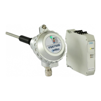
The FS750E system consists of two main components: a dust monitor (sensor) and a DIN-rail transmitter. The core principle of operation is based on the triboelectric effect. As particles move through a pipe or channel, they naturally become electrically charged due to collisions with each other or with the channel walls. When these charged particles fly near or touch the sensor rod of the FS750E, a charge transfer occurs, which is then detected by the sensor. This mechanism allows for reliable detection of particle loads, even in the presence of resting particles or deposits, which do not affect the measurement. This makes it suitable for subsequent installation into existing exhaust ducts without issues.
The sensor is connected to the transmitter via a 4-wire cable. The measured particle load is then processed by the transmitter and made available as a standard 4-20mA analog signal. This analog output allows for continuous monitoring of particle load. In addition to the analog output, the sensor provides a visual indication of three different particle load conditions through various LED colors.
The primary intended use of the FS750E is to detect malfunctions in filters, such as cracks, fractures, or assembly errors, by monitoring the dust levels on the clean air side. This provides automatic and reliable reporting of such issues.
Important Technical Specifications
Flow-Sensor FSS750E:
- Housing material: Aluminum
- Material sensor rod: V2A / V4A (option)
- Isolator: PPS
- Protection class: IP65
- Weight: 700g
- Tightening torque - mounting: 40Nm
- Storage temperature: -20°C to +70°C (not condensing)
- Operating temperature: -20°C to +70°C
- Process temperature: -20°C to +150°C
- Process pressure: 0 to 2 bar
- Supply voltage: 24 VDC (18 VDC ... 26 VDC)
- Power consumption: max. 50 mA
- Power: < 2 W
- Hysteresis: fixed
- Filter time: fixed
- Connection cable: pre-assembled (length 3.0 m, Ø 4.4 mm, 4 x 0.14 mm², insulation: PVC or special halogen-free compound)
Transmitter FS1750E:
- Analog output: Constant current 4-20 mA, max. 20.5 mA
- Load: max. 750 Ω
- Load influence: ≤ 0.02%
- Damping: filter 1st order, fixed
- DC voltage: 24 VDC, -20% to +30%
- Power consumption: max. 2 W
- Power-LED/green: good-condition of power supply
- Housing material: Polyamide
- Color: light grey
- Protection class: IP20
- Dimensions (Width x length x height): 22.5 x 115 x 108 mm (with connection terminal blocks)
- Inflammability class acc. to UL 94: V0
- Housing type for mounting: 35 mm DIN rails
- Weight with terminal blocks: approx. 100 g
- Connection terminal (Solid/Stranded wire min/max): 0.2 mm²/2.5 mm²
- AWG/kcmil (min/max): 24/14
- Stripping length: 7 mm
- Connection method: pluggable screw connection
- Tightening torque: 0.5 ... 0.6 Nm
Usage Features
- Easy Installation: The FS750E is designed for quick and easy installation. It requires welding a threaded sleeve into the pipe or channel. The sensor rod is then inserted into the pipe and fixed by the thread.
- Mounting Position: For optimal performance, the inlet and outflow zone for the FS750E should be at least 3 times the nominal diameter of the pipe. The sensor rod length should be at least 1/3 of the pipe diameter and must not touch the opposite wall, with a recommended minimum distance of 20mm between the rod end and the opposite wall. The threaded sleeve should be fixed at a 90° angle to the tube axis, with a reliable weld closing the gap between the sleeve and the pipe wall. An 18 mm drill bit is used for the measurement window, with the welded sleeve serving as a drilling template. After drilling, the borehole on the inner pipe wall needs to be trimmed to prevent material deposits.
- Earthing Connection: A proper earthing connection between the sensor enclosure and the installation location (pipe) is mandatory for correct device operation.
- Transmitter Mounting: The transmitter is designed for mounting on a 35 mm DIN rail (EN 60715) and should be installed in a suitable housing, preferably in a control cabinet or a dry room, to meet protection class requirements.
- Electrical Connection: The sensor and transmitter are connected via a pre-assembled 4-wire cable. The shield of the connection cable should be connected to the ground rail (DIN rail). The transmitter requires a 24V DC supply. The analog 4-20mA output uses terminal pins T2 and T4 (shared ground). Shielded connection cables are recommended, but unshielded cables can be used if the cable length is under 3m and the transmitter is in a control cabinet.
- Commissioning: After connecting the transmitter to the 24V power supply, the device undergoes a brief power-on procedure, indicated by a flashing blue LED on the sensor. During this time, the analog output signals 3mA. Once the procedure is complete, the device is ready for use, and the particle load measurement is output in the 4-20mA range.
- Calibration: The FS750E is pre-calibrated by the manufacturer. The analog output range can be customized using two adjustment options:
- Sensor Adjustment: The amplification factor of the sensor can be adjusted using a gain switch on the sensor board.
- Transmitter Adjustment: The ZERO and SPAN potentiometers on the DIN-rail transmitter allow for fine-tuning the analog output. The ZERO potentiometer maps the lower measuring range to 4mA, adjustable by up to 4mA. The SPAN potentiometer maps the upper measuring range to 20mA, also adjustable by up to 4mA. The current output is limited to a maximum range of 3.8mA to 20.5mA.
- Operation: The device continuously captures and outputs the particle load as an analog value according to the adjusted settings. A communication error between the sensor and transmitter will result in a 3mA output.
- Condition Indication: Different LED colors on the sensor provide additional visual signals for various particle load conditions.
Maintenance Features
- Maintenance-Free: The FS750E is designed to be maintenance-free under normal operating conditions.
- Long-Term Reliability: The transmission of the devices remains reliable and stable over a long period, requiring neither regular adjustments nor maintenances.
- Inspection for Abrasive Materials: When the device is used with abrasive materials, the product stream exposed areas should be regularly checked for their dimensions. The loss of material should not exceed 1mm.
- Fault Elimination: In case of a detected disturbance or malfunction, the device should be removed from operation and sent to the manufacturer for maintenance.
- Disposal: Packaging and used parts must be disposed of in accordance with the provisions of the country where the equipment is installed. Electronic components, in particular, are classified as hazardous waste.
The FS750E is a robust and reliable solution for monitoring filter integrity, providing both analog output for continuous process control and visual indications for immediate status awareness. It complies with the EMC Directive 2014/30/EU and the Low Voltage Directive 2014/35/EU, bearing the CE mark.