11
Operation
General System Operation
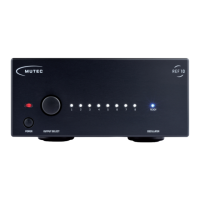
Operating the REF 10 is very straight-forward! Apart from the
two power switches there is only a single push button rotary
encoder (»OUTPUT SELECT«) used to individually turn the
eight outputs on or off. Per factory default all outputs are acti-
ve upon powering up the device for the first time, so all eight
white front panel LEDs will light up accordingly!
Selecting and toggling the outputs
The front panel encoder’s action is stepped and each step will
evoke a new setting. The push button function of the encoder
is used to toggle features.
Rotate the encoder by one step to select an output and the
first LED will start flashing. Turning the encoder by another
step now will cause the next LED to flash while the previous
one returns to a steady light. Thus, it is only possible to select
one output at a time.
As long as an LED is flashing, the respective output can be
toggled with a push of the encoder. When the LED is on, the
output is active. When the LED is off, the output has been di-
sengaged. Any setting will have immediate effect - it is not
necessary to take any further actions.
The last setting of the REF 10 will be stored and preserved
after the the device has been powered down.
Recommendations for the REF 10
To ensure a long-lasting performance with optimum clock si-
gnal quality that will best enhance your connected devices
we would like to share a few recommendations for using the
REF 10.
•
Prior to enjoying an in-depth listening session we recom-
mend pre-heating the REF 10 for about 20-30 minutes.
While the heater generally reaches its operating tempe-
rature in about five minutes, the entire oscillator section
takes longer to fully warm up. To ensure optimal perfor-
mance and highest frequency stability, you should grant
the REF 10 this additional warm-up time.
•
Keeping the REF 10 permanently powered up is generally
not required as long as you observe the extended warm-
up period described above. We do however advise against
power cycling the REF 10 in short, repeated intervals!
•
The REF 10 should always be placed away from mecha-
nically vibrating devices (such as turn tables). Although
the REF 10’s case feet of the are equipped with isolating
rubber rings, excessive structure-borne vibrations can
nonetheless interfere with the oscillator and negatively
affect the clock performance and signal quality.
The REF 10 should furthermore not be placed in close pro-
ximity to devices emitting strong electromagnetic fields
(such as fluorescent lamps). Even though the electronics
of the REF 10 are encapsulated in a steel enclosure these
strong electric fields can interfere with the sensitive elec-
tronics and also negatively affect the signal quality.
•
We generally recommend disengaging all clock outputs
that are not used for your given setup to reduce potential
interference as much as possible. Additionally, unused
and disengaged outputs can be fitted with so-called BNC
termination plugs. These are available from retailers with
both 50 and 75 Ω matching both of the REF 10s output
terminations.