15
10 MHz Compatible Products
Appendix
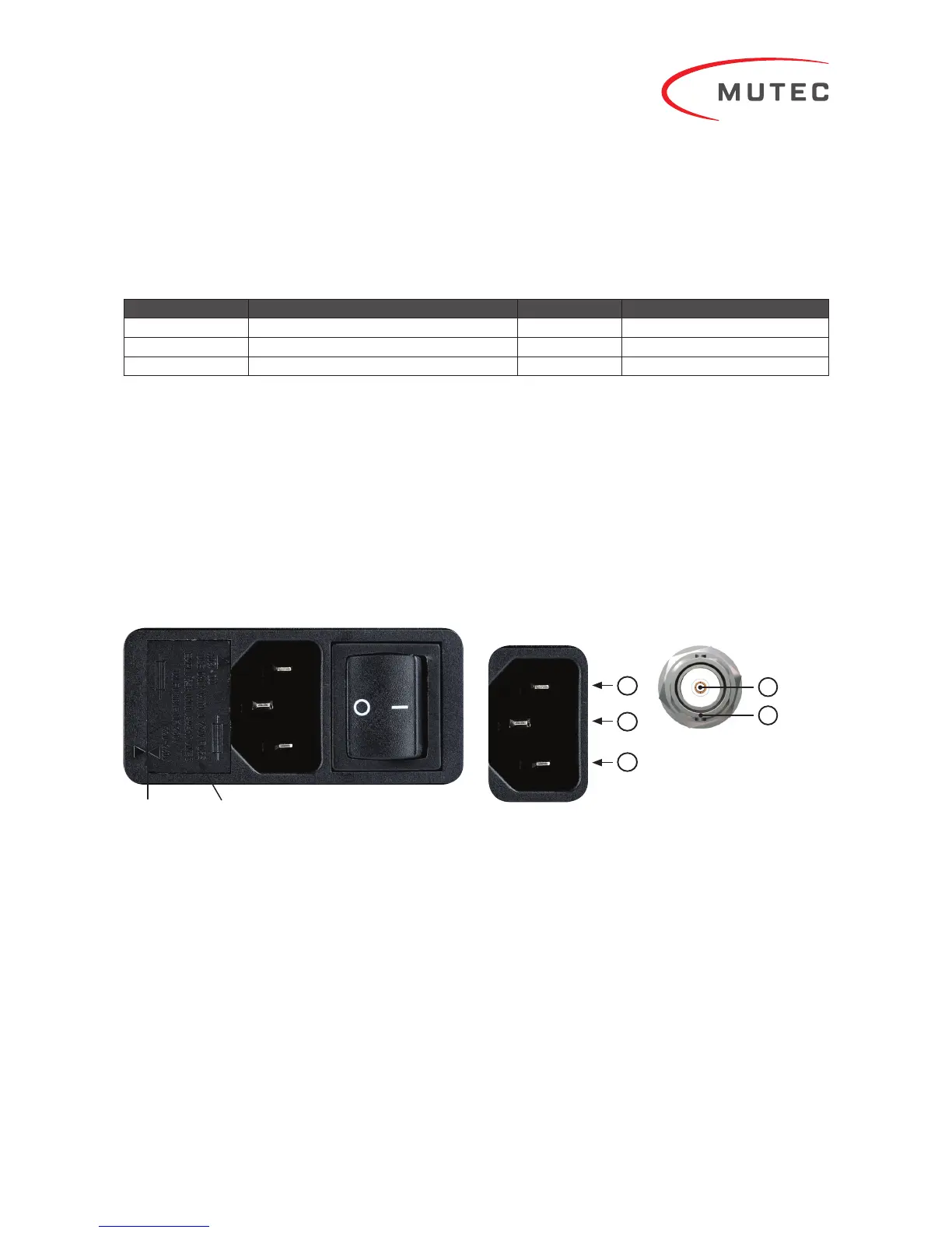
Changing the Line Voltage
Always unplug the mains cable before changing the line
voltage fuse!
On the left hand side of the mains power module on the rear
you will see two small triangles facing each other (see left
arrow in picture above). The respective line voltage »110-120
V« or »220-240 V« is printed above the right triangle. If this
setting should not be appropriate for your power grid, the fuse
holder (see right arrow in picture above) needs to be pulled
out, rotated by 180° around its own axis, and be put back in
place. You should then see that the triangle now indicates the
correct line voltage. It is easiest to remove the fuse holder by
inserting a small flat screwdriver in the groove on the right
side of the fuse holder to pull it outwards.
Make sure that the fuse holder is properly seated in its
housing with its top flush to the power!
Pin Assignment of the Terminals
Mains In
1) Neutral (N)
2) Protective Earth (E)
3) Live, Phase (P)
Technical Data
Interfaces:
•
2 x BNC, unbalanced, 50 terminated, buffert
•
6 x BNC, unbalanced, 75 terminated, buffert
Signal format of all clock outputs
•
Square wave, 10.000 MHz, 2 Vpp, 50:50 duty cycle
Clock Generation:
•
Type: 10.000 MHz ultra-low phase noise oven-controlled
crystal oscillator
•
Frequency accuracy when shipped: < ±0.01 ppm
•
Frequency stability vs. temperature range: < ±0.01 ppm
within -20 °C to +70 °C (-4 °F to +158 °F)
Fuse HolderTriangles
BNC-Ausgang 50/75 Ω
1) Signal
2) Ground
1
2
Manufacturer Product Impedance (Ω) Type
Tascam CG-1000, CG-1800, CG-2000 50/75 Audio/Video Clock Generator
Teac UD-503, NT-503 50 DAC, Network Player
TechDAS D-7, D-7i 50 DAC
Disclaimer: Compatibility of the REF 10 with the above listed products is assumed based on the specifications published by the respective manufacturers and subject to change.
MUTEC is not liable for compatibility issues with third-party products operating outside of industry standards.