2202MYJE-MY-C8-N_2018.02.
Chapter 5 Maintenance and Inspection
Compound 2-stage Screw Compressor 3225**C 5.5 Reassembly
5-55
m) After joining the flanges together, tighten the hexagon socket head cap screws [24] of the balance
piston cover at the specified torque of 90 N・m and tighten the hexagon socket head cap screws
[62-2] of the unloader cylinder at the specified torque of 240 N・m.
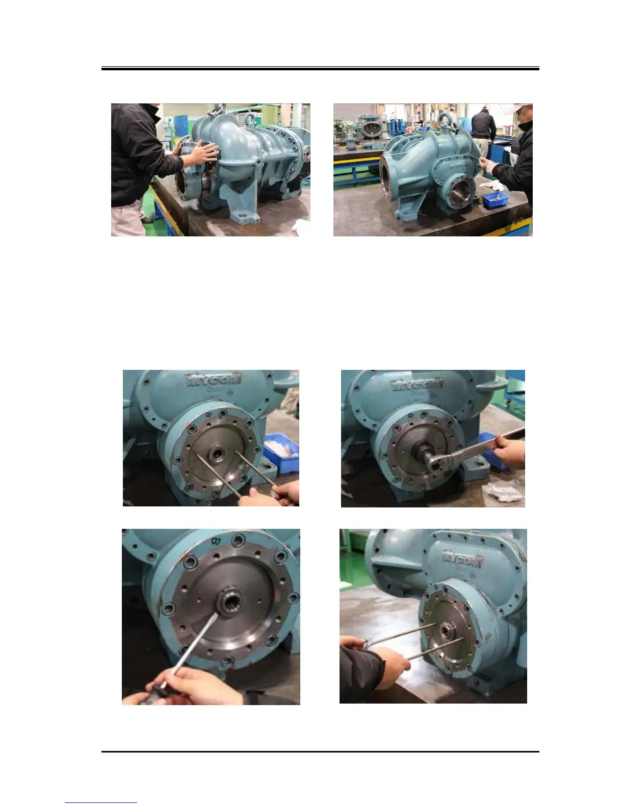
n) Use the eye bolts to pull the piston toward you (Photo 098), once remove the temporarily fastened
lock nut, install the lock washer [70-2] and lock nut [69-2], and then tighten the lock nut at the
specified torque of 140 N・m. To prevent loosening, bend the tooth of the lock washer at the notch of
the lock nut (Photo 100). Lastly, use the eye bolts to check the smooth movement of the piston
(Photo 101).