2202MYJE-MY-C8-N_2018.02.
Chapter 5 Maintenance and Inspection
Compound 2-stage Screw Compressor 3225**C 5.4 Disassembly and Inspection
5-20
5.4.3 Unloader Piston and Unloader Cylinder
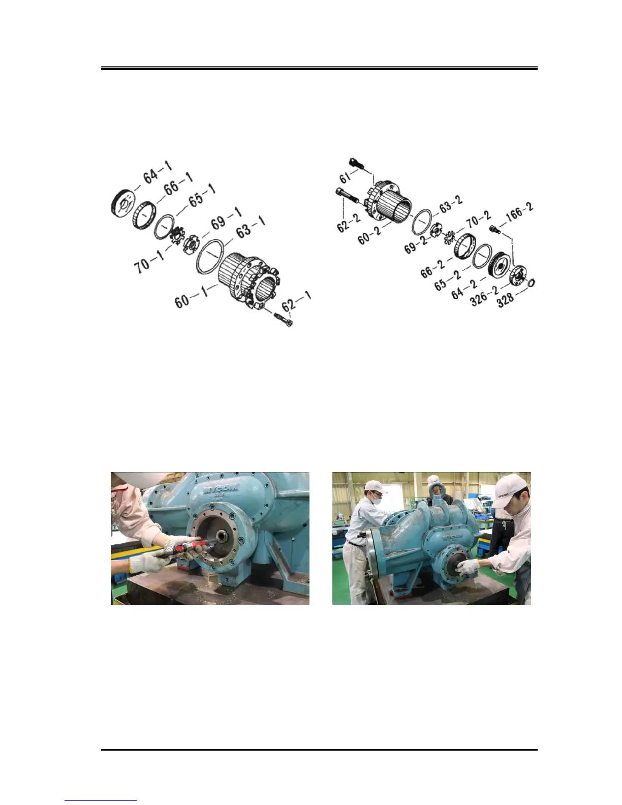
Inside the unloader cylinder [60-1] [60-2] is an unloader piston [64-1] [64-2] around which the cap seal
[66-1] [66-2] and O-ring [65-1] [65-2] are fitted. The unloader piston is assembled to the unloader push
rod [67-1] [67-2], which operates the unloader slide valve, with the lock nut [69-1] [69-2].
Figure 5-5 Unloader Cylinder Block
(Low-stage)
Figure 5-6 Unloader Cylinder Block
(High-stage)
5.4.3.1 Disassembly
a) Screw two M8 eyebolts into the threaded holes of the unloader piston [64-1] [64-2], and pull it fully
towards you.
b) Unbend the locking tooth of the lock washer [70-1] [70-2], which is used to fix the piston on the push
rod, such that the lock nut [69-1] [69-2] can be turned. Then, loosen and remove the lock nut.
c) Now, you can remove the unloader piston.
Photo 015: Release the Locking Tooth
of the Lock Washer (High-stage)
Photo 016: Use Lock Nut Wrench
to Loosen the Lock Nut
(High-stage)