2202MYJE-MY-C8-N_2018.02.
Chapter 5 Maintenance and Inspection
Compound 2-stage Screw Compressor 3225**C 5.5 Reassembly
5-58
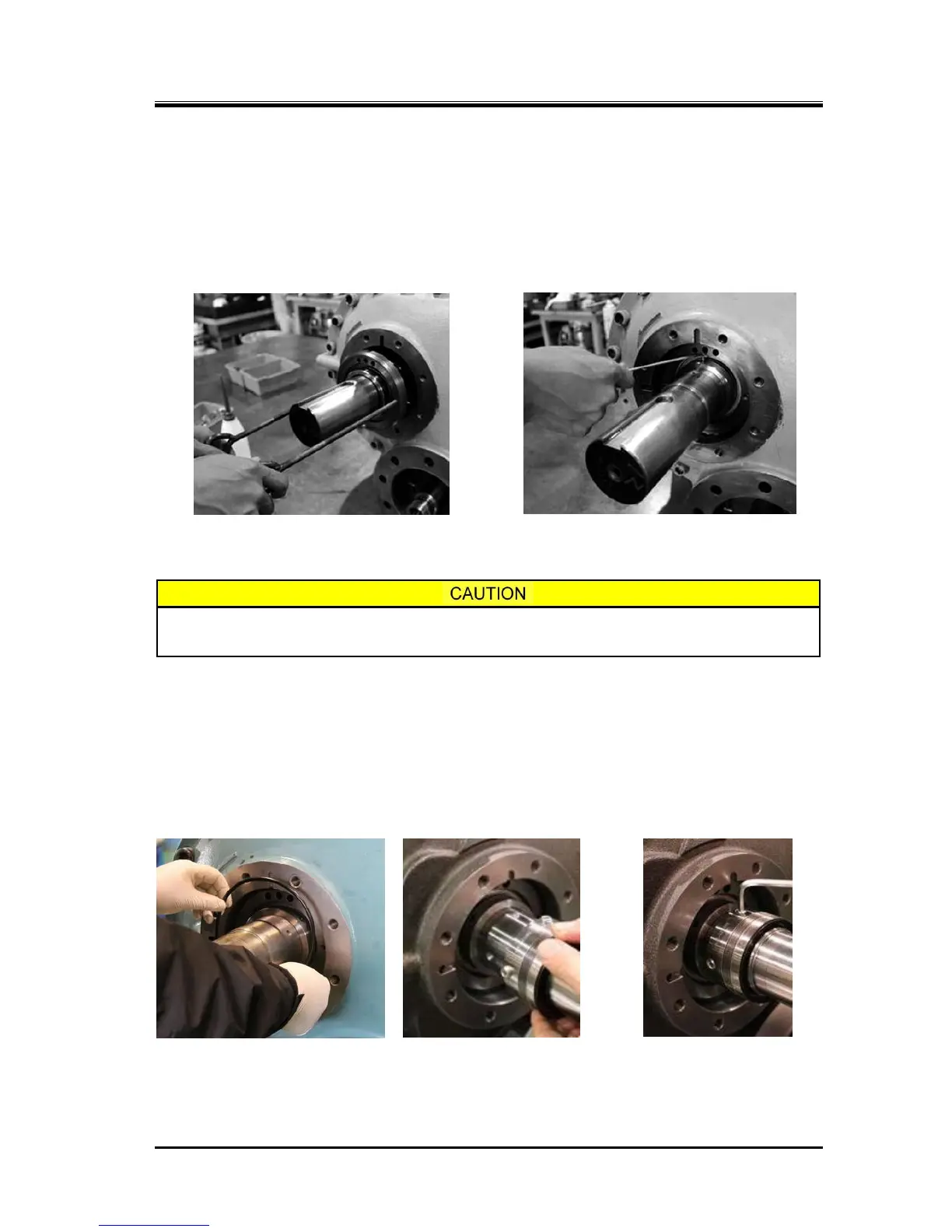
d) Install the oil seal retainer with the oil seal and sleeve along the rotor shaft using two M8 eye bolts
as shown in Photo 107. At this time, position the oil escape hole of the retainer on the upper side of
the rotor shaft, and accurately align the notch in the retainer with the position of the spring pin [20]
that is driven in into the bearing cover to prevent its rotation.
After the installation, check the position by slightly turning the retainer to the left and the right using
the eye bolts. If the position is correct, the retainer will not rotate.
e) Secure the oil seal sleeve using two set screws [529] on the rotor shaft (Photo 108).
f) Then, insert the O-ring for the seal retainer [49] (Photo 109).
You should be particularly careful on this point, as the O-ring for the oil seal retainer
[49] is often forgotten to be installed.
g) Insert the O-ring [112] on the inner circumference of the seal collar [109], and install the seal collar
on the rotor shaft. Before the assembly, apply sufficient lubricating oil onto the rotor shaft and wash
out dust and stains. Push in the seal collar carefully not to damage the O-ring [112] by the step on
the rotor shaft (Photo 110). After installing the seal collar, push it by hand and check it’s normal
movement in the axial direction.
h) Fasten the seal collar on the rotor shaft by screwing the two seal collar set screws [111] at the
countersinks on the rotor shaft (Photo 111). Failing to fasten the screws at the countersink positions
will damage the rotor shaft, and it can cause a leakage.