2202MYJE-MY-C8-N_2018.02.
Chapter 2 Compressor Specifications and Structure
Compound 2-stage Screw Compressor 3225**C 2.3 Compressor Specifications
2-3
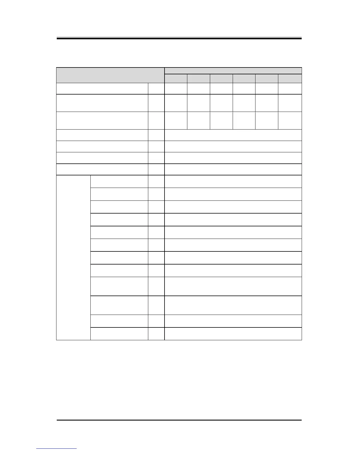
Table 2-2 3225**C Screw Compressor Specifications (1/2)
Low-stage swept volume
@3550 min
-1
/2950 min
-1
High-stage swept volume
@3550 min
-1
/2950 min
-1
Ammonia, Hydrofluorocarbon, etc.
Capacity control (Actual load)
Counterclockwise viewed from motor
Low-stage discharge
flange
High-stage suction
flange
High-stage discharge
flange
Journal lubrication
(low-stage)
Journal lubrication
(High-stage)
Oil injection
lubrication
Oil return Inlet
(Rotor casing)
Oil return outlet
(Low-stage Bearing
cover)
Oil return outlet
(High-stage Suction
cover)
Low-stage capacity
control
Load: Rc3/8, Unload: Rc3/8
High-stage capacity
control
Load: Rc3/8・Rc1/2, Unload: Rc3/8
Unless otherwise noted, the pressure unit MPa represents the gauge pressure
in this manual.
For limits of working temperature and pressure, see "2.3.2 Operation Limits" in
this manual.