Appendix 1-5
1-7 Power Supply and Control Devices
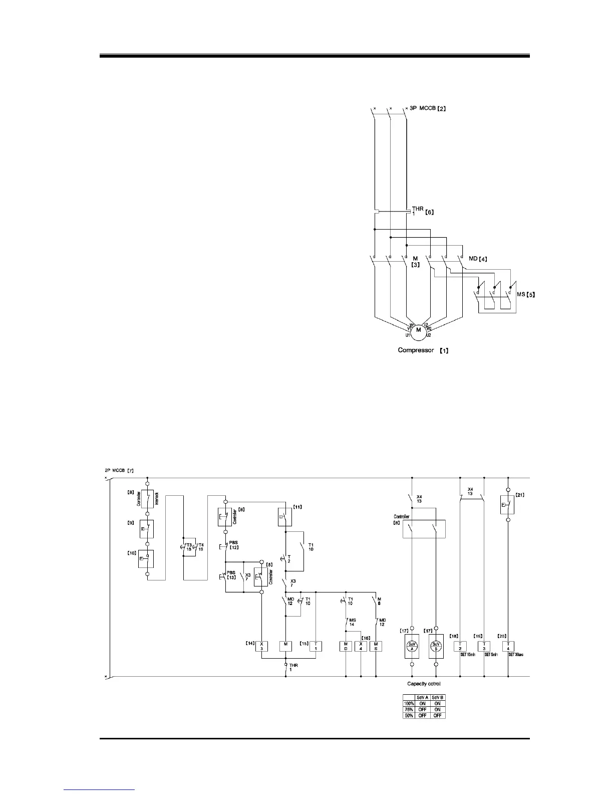
An example of a standard power control circuit diagram
(star-delta starting) is shown in Figure app.1-8a and Figure
app.1-8b.
In the package unit using i-series compressor, you can
choose a variety of motor starting method such as direct
on-line starting, using a frequency inverter, star-delta starting,
using a soft starter, etc. according to the type of motor.
When selecting wires, electromagnetic contactors and fuses,
ask their information to the motor manufactures and adopt
proper ones to the motor specifications.
Reference:
[1]: Main Motor [2]: Main Power Source Switch
[3]: Electromagnetic Contactor (main)
[4]: Electromagnetic Contactor (delta)
[5]: Electromagnetic Contactor (star)
[6]: Thermal Switch [7]: Control Power Source Switch
[8]: Various Control Contact (other control circuit)
Note: [9] , [10], [11] and [21] are Contacts of Protection
[9]: Protection from abnormally High Discharge Temperature
[10]: Protection from abnormally High Discharge Pressure
[11]: Protection from abnormally High Suction Pressure
[12]: Switch for Operation Stop [13]: Switch for Operation Start
[14]: Relay for Operation Start/Stop [15]: Star-Delta Timer
[16]: Relay for Confirmation of Compressor Start-up [17]: Solenoid Valve for Capacity Control
[18]: Timer for Protection from Motor Re-starting
[19]: Timer for Protection from Low Oil Supply Pressure at the Compressor Start-up
[20]: Timer for Protection from Low Oil Supply Pressure
[21]: Contact of Protection from Low Oil Supply Pressure