EasyManua.ls Logo

mycom i160M

Default Icon
121 pages
To Next Page IconTo Next Page
To Previous Page IconTo Previous Page
Loading...
2203M4-JE-MY-iS2-N_2017.04.
Chapter 2 Compressor Specifications and Configuration
Screw Compressor i-series 2.4
Configuration of Compressor
2-32
P/N
Part name Code No. Remarks
Qty
553
Chuck Union
KD122-10E
I-Φ10-R1/4 KZC10-050E
1
554
Angle Valve
NF067-02
TC-1 R1/4×Rc1/4
1
555
Angle Valve
NF067-03
TC-1 R3/8×Rc1/4
1
556
Connection (I-type)
NJ2-1003NE
I-Φ10-R3/8
1
557
Piping
QA1802-10
Φ10 STS
1
558
Hexagon Bushing
NF031-0403
JO5007 R1/2×Rc3/8
1
559
Hose Nipple
NN5102-050
8A×50
1
795
Cover Plate, Discharge Flange
CS71500-I1601 i160 4.5x146D
794 Cover Plate, Suction Flange
CS71500-I1602 i160 4.5x213D
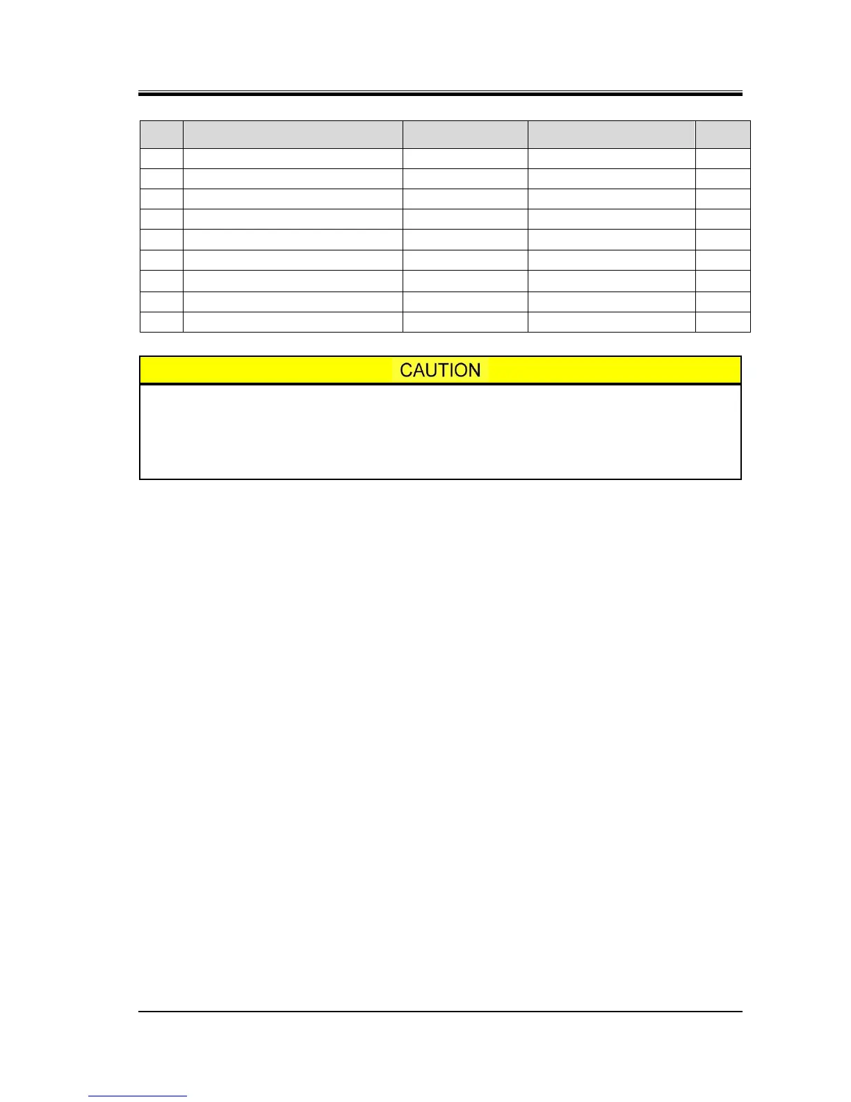
The part code of the O-ring is the one assigned to NBR-70-1 which is standard
material. When the material of the O-ring is other than NBR, a different part code is
used for each material.
If you are using O-rings made from other than the standard material, please
contact MAYEKAWA when placing an order.

Related product manuals